MIL-STD-883 method 2004.7 – Test condition B1: Bending stress
Purpose
This test is designed to check the capability of the leads, lead welds, and seals of the devices to withstand stresses to the leads and seals which might reasonably be expected to occur from actual handling and assembly of the devices in the application, or to precondition the leads with a moderate bending stress prior to environmental testing.
Apparatus
Attaching devices, clamps, supports, or other suitable hardware necessary to apply the bending stress through the specified bend angle.
Procedure
Each lead or terminal to be tested shall be subjected to a force as specified in 3.1 through 3.5, as applicable. Any number or all of the leads of the device may be tested simultaneously. Rows of leads may be tested one row at a time. Each lead shall be tested in one direction and returned to the approximate original position. All arcs shall be made in the same plane without lead restriction.
Direction of bends
Test leads shall be bent in the least rigid direction. If there is no least rigid direction, they may be bent in any direction. No lead shall be bent so as to interfere with another lead. If interference is unavoidable, the test lead shall be bent in the opposite direction to the angle specified and returned to its approximate original position.
Procedure for pre-formed leads
When normally straight leads are supplied in a pre-formed condition (including the staggered lead dual-in- line configuration), the lead forming operation shall be considered an acceptable bending stress in place of that specified, provided the lead forming has been done after lead plating and the forming is at least as severe in permanent lead deformation as the specified bending.
Procedure for flexible and semi-flexible leads (e.g., flat packs and axial-lead metal-can devices)
Flexible leads
Flexible leads shall be bent through an arc of at least 45° measured at the lead extremities, unless otherwise specified.
Semi-flexible leads
Semi-flexible leads shall be bent through an arc of at least 30° measured at the lead extremities unless otherwise specified.
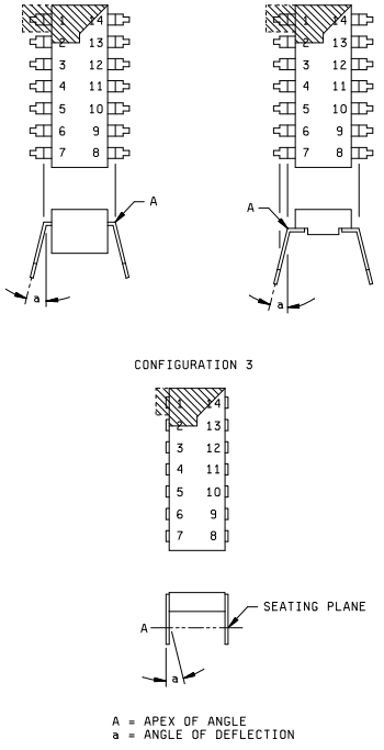
Procedure for dual-in-line and pin grid array package leads
Dual-in-line (platform, side brazed, bathtub) package leads are leads normally aligned in parallel at a 90° angle from the bottom of the package during insertion. Dual-in-line package leads shall be bent inward through an angle sufficient to cause the lead to retain a permanent bend (i.e., after stress removal) of at least 15°. For configuration 1 and 2, the angle of bend shall be measured from the lead extremities to the first bend (see figure 2004-1), for configuration 3, the angle of bend shall be measured from the lead extremities to the seating plane (see figure 2004-1).
Pin grid array packages shall have the leads required for testing from the outside row of leads on opposite sides bent through an angle sufficient to cause the lead to retain a permanent bend (i.e., after stress removal) of at least 15°. The angle of bend shall be 15° from normal and the bend shall be made at the approximate seating plane.
Procedure for rigid leads or terminals
Unless otherwise specified in the package acquisition document, devices with rigid leads or terminals shall be bent through an angle of at least 10° to cause a permanent bend (i.e. after stress removal).
Note: Rigid leads or terminals shall be reviewed by the acquiring device manufacturer to determine if a lead integrity test adds value based on the purpose of this test condition.
Failure criteria
When examined using magnification between 10X and 20X after removal of the stress, any complete breakage (e.g. separation of the lead from the body) or loosening of the lead at the glass/ceramic seal that has caused a method 1014 seal failure shall be considered a failure. When a seal test in accordance with method 1014 is conducted as a post test measurement following the lead integrity test(s), glass meniscus cracks shall not be cause for rejection of devices which pass the seal test.
Summary
The following details shall be specified in the applicable acquisition document: