MIL-STD-883 method 2019.9 – Die shear strength
Purpose
The purpose of this test is to determine the integrity of materials and procedures used to attach semiconductor die or surface mounted passive elements to package headers or other substrates. This determination is based on a measure of force applied to the die, the type of failure resulting from this application of force (if failure occurs) and the visual appearance of the residual die attach media and substrate/header metallization.
Apparatus
The test equipment shall consist of a load-applying instrument with an accuracy of ±5 percent of full scale or 50 grams, whichever is the greater tolerance. A circular dynamometer with a lever arm or a linear motion forceapplying instrument may be used to apply the force required for testing. The test equipment shall have the following capabilities:
- A die contact tool which applies a uniform distribution of the force to an edge of the die (see figure 2019-1). A compliant (conforming) material (e.g., nail polish, tape, etc.) may be applied to the face of the contact tool to ensue uniform force distribution on the edge of the die.
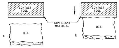
Figure 2019-1 Compliant interface on contact tool distributes load to the irregular edge of the die</figcaption - Provisions to assure that the die contact tool is perpendicular to the die mounting plane of the header or substrate.
- A rotational capability, relative to the header/substrate holding fixture and the die contact tool, to facilitate line contact on the edge of the die; i.e., the tool applying the force to the die shall contact the die edge from end-to-end (see figure 2019-2).
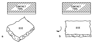
Figure 2019-2 Rotate the die contact tool or the device for parallel alignment - A binocular microscope with magnification capabilities of 10X minimum and lighting which facilitates visual observation of the die and die contact tool interface during testing.
Procedure
The test shall be conducted, as defined herein, or to the test conditions specified in the applicable specific acquisition document consistent with the particular part construction. All die strength tests shall be counted and the specific sampling, acceptance, and added sample provisions shall be observed, as applicable.
Shear strength
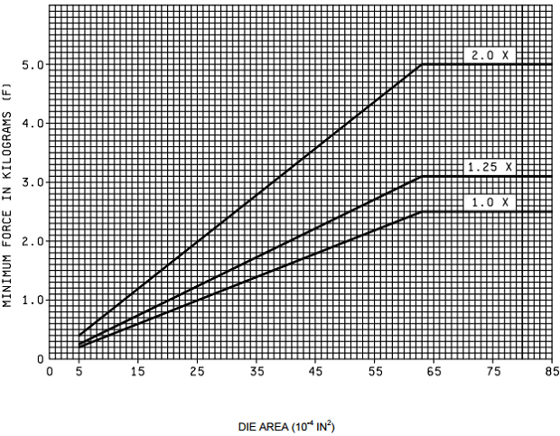
A force sufficient to shear the die from its mounting or equal to twice the minimum specified shear strength (figure 2019-4), whichever occurs first, shall be applied to the die using the apparatus of 2 above.
Note: For passive elements only attached at the end terminations, the area used to determine the force applied shall be the total area of the mounting surface of the end terminations. An area between end terminations filled with nonadhering filler shall not be used to determine the force applied. However, any adhering material applied between the end terminations shall be used in the shear calculation. If the area between end terminations contains an adhering material, then the area of the adhering material shall be added to the area of the mounting surfaces of the end terminations and that total area shall be used to determine the force applied.
- When a linear motion force-applying instrument is used, the direction of the applied force shall be parallel with the plane of the header or substrate and perpendicular to the die being tested.
- When a circular dynamometer with a lever arm is employed to apply the force required for testing, it shall be pivoted about the lever arm axis and the motion shall be parallel with the plane of the header or substrate and perpendicular to the edge of the die being tested. The contact tooling attached to the lever arm shall be at a proper distance to assure an accurate value of applied force.
- The die contact tool shall apply a force gradually from zero to a specified value against an edge of the die which most closely approximates a 90° angle with the base of the header or substrate to which it is bonded (see figure 2019-3). For rectangular die, the force shall be applied perpendicular to the longer side of the die. When constrained by package configurations, any available side of the die may be tested if the above options are not available.
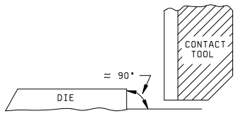
Figure 2019-3 The contact tool shall load against that edge of the die which forms an angle ≈ 90° with the header/substrate - After initial contact with the die edge and during the application of force, the relative position of the contact tool shall not move vertically such that contact is made with the header/substrate or die attach media. If the tool rides over the die, a new die may be substituted or the die may be repositioned, provided that the requirements of figure 2019-3 are met.
Failure criteria
A device which fails any of the following criteria shall constitute a failure.
Note: (See examples for determining DIE AREA following figure 2019-4.)
Epoxy attach
- Fails die strength requirements (1.0X) of Figure 2019-4.
- Separation occurs with a strength greater than the minimum (1.0X) specified in Figure 2019-4, but with less than 2.0 times that strength and evidence that less than 75 percent of the die to substrate contact area contained attach medium coverage. Evidence of adhesion will be in the form of attach medium to the intended area on the substrate, the element or combination of both.
Note: Residual element material (silicon or other) attached in discrete areas of the die attach medium shall be considered as evidenced of adhesion.
Eutectic, solder, and other attach
- Fails die strength requirements (1.0X) of Figure 2019-4.
- Separation occurs with a strength greater than or equal to the minimum (1.0X) specified in Figure 2019-4, but with less than 1.25 times that strength and evidence that less than 50 percent of the die to substrate contact area contained attach medium coverage. Evidence of adhesion will be in the form of attach medium to the intended area on the substrate, the element or combination of both.
- Separation occurs with a strength greater than or equal to the 1.25X specified in Figure 2019-4, but with less than 2.0 times that strength and evidence that less than 10 percent of the die to substrate contact area contained attach medium coverage. Evidence of adhesion will be in the form of attach medium to the intended area on the substrate, the element or combination of both.
NOTE: Residual element material (silicon or other) attached in discrete areas of the die attach medium shall be considered as evidence of adhesion. For metal glass die attach, die attach material on the die and on the package base shall be considered as evidence of acceptable adhesion.
Separation categories
When specified, the force required to achieve separation and the category of the separation shall be recorded.
- Shearing of die with residual silicon remaining.
- Separation of die from die attach medium.
- Separation of die and die attach medium from package.
Summary
The following details shall be specified in the applicable acquisition document.
Notes:
- All die area larger than 64 x 10-4 (IN)2 shall withstand a minimum force of 2.5 kg or a multiple there of (see 3.2).
- All die area larger than or equal to 5 x 10⁻⁴ (IN)2 but smaller than or equal to 64 x 10-4 (IN)2 shall withstand a minimum force as determined from the chart of figure 2019.4. The chart is based on a force of 0.04 kg forevery one ten-thousandth (10-4) square inch at (1X) level. Similarly, the required minimum force is 0.05 kgfor every 10-4 IN2 at (1.25X) level and is 0.08 kg for every 10-4 IN2 at (2X) level.
- All die area smaller than 5 x 10⁻⁴ (IN)2 shall withstand a minimum force (1.0X) of 0.04 kg/10-4 (IN)2 or a minimum force (2X) of 0.08 kg/10-4 (IN)2.
Examples of determining die strength requirements based on die area
Example 1
Die Area of device measuring .02 inches by .02 inches.
Die Size = .02 X .02 = .0004 IN2 = 4 X 10⁻⁴ (IN2).
Because die size is less than 5 X 10⁻⁴ (IN2) use Note 3 which states the value of minimum force required is 0.04kg/10-4 (IN2) at (1X), 0.05 kg/10-4 (IN2) at (1.25X), or 0.08 kg/10-4 (IN2) at (2X). Thus the associated minimum forces required are 0.16 kg, 0.20 kg and 0.32 kg, respectively.
Example 2
Die Area of device measuring .04 inches by 0.04 inches.
Die Size = .04 X .04 = .0016 IN2 = 16 X 10-4 (IN2).
Because die size is between 5 X 10⁻⁴ (IN2) and 64 X 10-4 (IN2) use Note 2 which states the value of minimum force required is to be determined based on the chart. The values for die size 16 X 10-4 (IN2) are found on the chart by reading 16 on the (10-4 IN2) scale, then finding the coordinating force value on the (F) scale. Doing so provides minimum forces required as .64 kg at (1X), .80kg at (1.25X), and 1.28 kg at (2X).
Alternately: The chart is based on using .04kg/10-4 (IN2) at (1X), .05 kg/10-4 (IN2) at (1.25X), and .08 kg/10-4 (IN2) at (2X). Thus: the minimum forces required are 16 X .04 = .64 kg (1X), 16 X .05 = .80 kg (1.25X), and 16 X.08 = 1.28 kg (2X).
Example 3
Die Area of device measuring .09 inches by .09 inches.
Die Size = .09 X .09 = .0081 IN2 = 81 X 10-4 (IN2).
Because die size is larger than 64 X 10-4 (IN2) use Note 1 which states the value of minimum force required is 2.5kg or a multiple thereof. Therefore, the minimum forces required are 2.5 kg at (1X), 3.125 kg at (1.25X), and 5.0 kg at (2X).
End of 2019.9
Learn more about die shear and see a videos of real tests.