MIL-STD-883 method 2023.7 nondestructive bond pull
Purpose
The purpose of this method is to reveal nonacceptable wire bonds while avoiding damage to acceptable wire bonds. This procedure is applicable for all bonds made by either ultrasonic or thermal compression techniques, except those larger than 0.005 inch diameter (or equivalent cross section area) that do not have sufficient clearance to permit use of a hook.
The alternate procedure defined in 3.2 may be used for devices with packages having 84 or more external terminations and with nominal bonding wire pitch at the package post of less than or equal to 12 mils.
Apparatus
The apparatus of this test shall consist of suitable equipment for applying the specified stress to the bond, lead wire or terminal as required in the specified test condition. A calibrated measurement and indication of the applied stress in grams force (gf) shall be provided by equipment capable of measuring stresses up to twice the specified limit value, with an accuracy of ±5 percent or ±0.3 gf, whichever is greater.
-
- The diameter of the wire used to make the hook utilized to apply force to the interconnect wire shall be as follows:
Wire diameter Hook diameter (x wire dia) ≤ 0.002 inch 2.0 x min > 0.002 inch – ≤ 0.005 inch 1.5 x min > 0.005 inch 1.0 x min For ribbon wire, use the equivalent round wire diameter which gives the same cross sectional area as the ribbon wire being tested. Flat portion of hook (horizontal) shall be >1.25 x the diameter of the wire being tested.
- The hook shall be smooth and free of defects which could compromise the test results or damage the wire being pulled.
- Travel speed of the hook shall be controlled to that impact loading as the hook initially contacts the wire shall be no more than 20 percent of the specified nondestructive bond pull force.
- Final hook placement shall be accomplished under observation at 15X minimum magnification. A microscope with a zoom capability may be used for indexing the hook.
- The fixturing which holds the package shall allow positioning the hook for optimum force application to the wire.
- An indicator shall either (1) measure the force required to cause failure of the interconnect; or (2) provide visual indication that the predetermined load has been applied.
- The hook shall be in a fixed position which restricts motion along a straight line between each bond, so that it will not rise to the highest point which could result in a test for only one bond (e.g., as for a ball bond)
- The diameter of the wire used to make the hook utilized to apply force to the interconnect wire shall be as follows:
Procedure
The test shall be conducted as specified in the applicable acquisition document, as a sample or as a screen, and shall be consistent with the particular bond materials and construction. All bond wires in each device shall be pulled and counted, and the specified sampling, acceptance, and added sample provisions shall be observed, as applicable. Where there is any adhesive, encapsulant or other material under, on, or surrounding the wire such as to increase the apparent bond strength, the test shall be performed prior to the application of the material.
- Set the rate of force application.
- Mount the specimen to be tested and set the lifting mechanism to apply the specified force for the appropriate wire size and material.
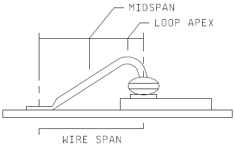
- The device shall be rotated and positioned such that the hook contacts the wire between midspan and loop apex without causing adverse wire deformation (for forward wedge and ball bonding, this would be between midspan and die edge; for reverse bonding, this would be between midspan and package edge) and the pulling force is applied in a perpendicular direction to the die or substrate surface. See Figure 2023-1.
- The lifting mechanism shall be actuated to stress the wire bond such that the specified stress is applied with minimum impact loading and with no overshoot greater than specified accuracy of the indicator at any time during the bond pull. The dwell time of maximum force application shall be a maximum of one second.
- Observe whether the bond breaks.
- If the bond breaks, reject the device and proceed to the next device, unless rework is acceptable. If so, record the identification of the broken bond and the device containing the bond. If rework is permitted, all bonds shall be tested prior to any bond rework and reworked bonds shall be tested.
- If no bonds on the device break, accept the device as satisfactory.
- Repeat a through g for all bonds to be tested.
- Record the total number of wires or wire bonds that fail when subjected to the predetermined stress.
- Record the number of devices that failed the test.
Failure criteria
Any bond pull which results in separation (of bonds at the bond interface or breakage of the wire or interconnect anywhere along the entire span including bond heels) at an applied stress less than the specified stress for the applicable material and construction shall constitute a failure. Unless otherwise specified, the applied nondestructive pull stress shall be 80 percent of the preseal minimum bond strengths for the applicable material, size and construction given in table I of method 2011 or figure 2011-2 of method 2011. Table I herein lists pull force values for commonly used wire sizes.
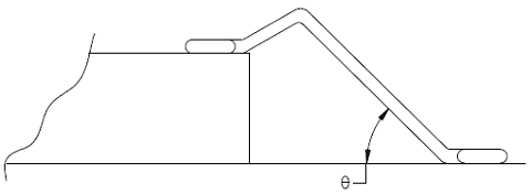
Note: RF/microwave hybrids that require extremely flat loops which may cause erroneous wire pull data may use the following formula to determine the proper wire pull value.
V1 = V2 sin Θ
Where:
V1 = New Value to pull test.
V2 = Table I value for size wire tested
Θ = Greatest calculated wire loop angle (Figure 2023-2).
Also, RF/microwave hybrids that contain tuning wires (designated wires that will alter RF performance when moved) or wires that cannot be accessed with a pull hook must be simulated on a test coupon in such a way to allow hook access for purposes of pull testing. These wires are to be bonded at the same time the production hybrids are bonded using the same setup, operator, schedule, and elements (electrical rejects may be used). The test coupon wires are to be pull tested in lieu of the tuning or inaccessible wires on the production hybrid. Failures on the test coupon shall be considered as failures to production units and appropriate action is to be taken in accordance with the applicable specification (figure 2023-3).

Alternative procedure
This alternate procedure may be used where 100 percent non-destructive bond pull cannot be performed because of high pin count (greater than or equal to 84 terminals) and small bonding wire pitch at the package post (less than or equal to 12 mils).
In-process controls
In order for a manufacturer to use the alternate procedure, a SPC program shall be implemented for the wire bond operation in accordance with TechAmerica EIA-557, Statistical Process Control Systems. Any change in the various effects shown to be significant by the characterization with respect to wire bond strength shall require a re-characterization of the wire bonding process for the changed effect(s) on wire bond integrity. For QML, the SPC program and the requirements listed herein shall be approved by the qualifying activity and may be subject to an audit at any time by the government qualification activity. For Non-Jan devices, the SPC program and the requirements listed herein are subject to review by the government agency responsible for the acquisition or their designee. All statistical evaluation, characterizations, and designed experiments shall be available for review.
Applicable incoming materials
Applicable incoming materials including wafer pad metallization targets, package bonding post, and bonding wire shall have their critical characteristics determined and made requirements for acceptance using either incoming inspection or vendor SPC data. Critical characteristics shall include possible sources of material contamination (e.g. excessive carbon content in aluminum wire). Also, the applicable incoming inspection requirements of MIL-PRF-38535 or MIL-PRF-38534 shall apply.
Applicable manufacturing processes
Applicable manufacturing processes including bond pad metal disposition, glassivation etch, and worst case package seal excursion shall have their critical characteristics determined and placed under SPC control. Also, the process control requirements of the applicable general specification shall apply for these operations including contamination controls, preventative maintenance procedures and schedules, and complete removal of glassivation from the bonding pad.
For packages with gold plated posts
For packages with gold plated posts, the device manufacturer shall perform a bake test on one device from each incoming package lot. This test shall evaluate for basic plating or contamination anomalies of the package post. The package shall be wire bonded post-to-post. The wire bonded package shall be baked at 300 degrees Celsius for 1 hour in either air or inert atmosphere. Bond strength shall then be tested in accordance with MIL-STD-883, method 2011, using a sample size number = 45, C = 0 on the number of wires pulled. If any bond strength failure is determined to be package plating or contamination related then the package lot shall not be used for this alternative unless the defect can be effectively screened and the package lot resampled to a tightened sample size number = 76, C = 0 for the number of wires pulled.
An active foreign material control program
An active foreign material control program shall be in accordance with MIL-STD-883, method 2010 or method 2017. A procedure and system for storing and handling wafers, packages, related piece parts, and unsealed devices that will prevent contamination through package seal including face masks, lint free gloves, restrictions on particle generating make-up, hair covers, and cleanroom gowns.
A 100 percent pre-bond visual inspection procedure
A 100 percent pre-bond visual inspection procedure of the die pads and package post shall be documented. The visual inspection shall be performed at 100-200X in an ISO 14644-1, Class 5 environment. Cleaning to remove rejectable contamination is allowed. No device shall exhibit evidence of the following criteria:
- Glassivation on the designed open contact area of the bond pads.
- Chemical, film, photoresist or liquid contamination on the pads or posts.
- Particulate and /or foreign material contamination on the pads or the critical bond area of the posts greater than 0.25 mils in diameter.
- Die pads and package posts that do not meet all applicable requirements of MIL-STD-883, method 2010, condition A or method 2017.
Note: 100 percent pre-bond visual inspection may be waived by the qualifying activity provided a 100 percent pre-clean of pads and posts is performed, and all pads and posts for five (5) randomly selected devices pass the inspection criteria. Precleaning may also be waived by the qualifying activity if historical data demonstrates the cleaning is unnecessary. No cleaning is allowed during sample inspection. A 100 percent pre-clean and sample inspection of 5(0) may be repeated a maximum of two times. Rejection of the sample after the second pre-clean shall result in a 100 percent pre-bond inspection of the lot in accordance with 3.2.1.5. An investigation of the rejects in the lot and sample shall be required and corrective action, as necessary shall be instituted. Until then, 100 percent pre-bond inspection is required. Once the effectiveness of any corrective action has been determined, the 100 percent prebond inspection may be eliminated.
Bonding machine parameters
Bonding machine parameters (e.g., temperatures, pressure, timing, fixtures, wire size, wire material, height settings, etc.) must be defined for each die/package combination. The bonding equipment parameters ranges shall be optimized by designed experiments. The experiments shall consider variations in bonding wire geometry (e.g., loop height, wire length, shelf height, etc.). The experiments shall establish the predicted strength and tolerance of the bonding operation. The allowable performance ranges of the bonding parameters determined by controlled experiments shall be documented. Equipment parameter changes outside the allowable limits must be evaluated and documented as to still meeting the predicted wire pull strength and tolerance.
Note: ASTM Standards F 458 and F 459 may be used as guideline documents.
Process capability study
After the wirebond process has been demonstrated to be in a condition of stability and statistical control, a process capability study shall demonstrate that the probability of any device failing the minimum post-seal bond strength is P < .0001. The probability must meet the accumulative probability at the device level and not at the individual wire level. The distributional form of the post-seal bond strengths shall be statistically evaluated for conformance to the selected sampling distribution (e.g., Gaussian, lognormal, Wiebull, etc.). The capability study sample size shall be sufficient to detect a shift in the distribution of the worst case package/die combination to a 100 parts per million level. The beta risk to the consumer shall be .001 or less. (See Appendix A for normal distribution example.) The process capability study shall be performed periodically. The capability study may be accomplished by characterizing the wire pull strengths of one or more worst case package/die combinations. Selection of the worst case package/die combinations should consider wire geometry, number of wires, pads and post sizes, etc. The characterization results from worst case package/die combinations must be readily extended to all devices.
Control limits and action procedures
The results of the evaluations in 3.2.1.6 and 3.2.1.7 shall be used in determining control limits and action procedures for the wire bond operation. A destructive wire bond strength sampling plan for each wire bonder shall include start and completion of each assembly lot, frequency of sampling the assembly lot, and changes in operators (manual wire bonding only), wire spools, package lots, or setup conditions. The bond strength data shall include the force required for failure, the physical location of failure, and the nature of the failure. Electrical rejects from the same wafer lot may be used for the destructive wire bond pulls. In the event that bond wire strengths are outside the predicted values for the wire, or class of wires with similar geometry, the bonder shall be inactivated immediately and not returned to production until tests show that the operation is back under statistical control. A procedure for the traceability, recovery, and disposition of all units bonded since the last successful bond strength test is required.
Time and temperature characterization
Initially, a time and temperature characterization shall be performed for each major type of wire bond metallurgical interface (e.g., gold/aluminum, etc.) to determine the electrical and mechanical integrity of the wire bonds with respect to such factors as; flexing of wire bonds due to thermal expansion, and microcracks or microvoids at the metallurgical interface. Evidence from the characterization shall demonstrate that the integrity of the bonds is sufficient for a device to function over its expected life. Life usage conditions shall exceed 50,000 cycles from a 0 – 85 degree Celsius temperature range at the bonds. Time and temperature degradation factors for accelerated testing must be justified against these minimal life usage conditions.
Wire bond integrity
If pre-burn-in, interim and post burn-in electrical failures (opens/shorts), qualification, or quality conformance inspection failures indicate questionable wire bond integrity then an analysis is required to verify the bond integrity. If any bond is confirmed to be defective; the applicable inspection lot or sublot will be rejected, an evaluation performed to determine the cause of the bond failure, corrective actions implemented based on the evaluation, and disposition of other affected inspection lots or sublots. The failure analysis and corrective actions will be retained and made available to the qualifying activity upon request.
Lot acceptance procedure
Each assembly lot shall receive a post-seal bond wire integrity acceptance test. A separate assembly lot acceptance test is required for each wire bonder, and for any changes in setup conditions, wire spool, package lot, or wafer lot, unless such differences have been demonstrated to be statistically insignificant. A post-seal destructive wire bond sampling and test plan with the following minimum requirements shall be documented.
- More than one device shall be subjected to the acceptance test. Electrical, non-wire bond related visual, or package seal rejects may be used for the post-seal wire bond test.
- The destructive wire pulls shall be evaluated in meeting the post-seal bond strength limits in MIL-STD-883, Method 2011, or as established in 3.2.1.7. The assembly lot shall be accepted if the wire bond strengths meet the requirements of sections c, d, and e below.
- All wires or a minimum of 50 randomly selected wires shall be pulled from each sampled device. The post-seal bond strength distribution(s) must demonstrate that the wire bond process is in statistical control, has not changed with respect to the distribution characterized for a one-sided lower control limit, and no single destructive pull is less than the specified post-seal bond strength limit. The sample size shall be sufficient to demonstrate that the statistical distribution of all wires pulled has not changed with respect to central tendency or dispersion in such a way as to violate a p < .0001 at the device level. The beta risk to the consumer shall be .01 or less. The method of statistical analysis shall be documented and approved by the qualifying activity.
- A minimum of 8 wires shall be evaluated from each sampled device to represent the worst case wires as determined to potentially violate the lower specification limit. Their wire pull strengths shall be within the predicted tolerances established in 3.2.1.6. Any wire pull strengths outside the predicted tolerance in the characterized distribution shall require evaluation as to the cause of the out of control condition, and additional worst case wires shall be pulled to determine whether the wire bond strength distribution meets a probability at the wire level of P < 1-[.9999**(1/n)] (n = number of bonding wires in the package). The lot is rejected if this criteria is not met.
- If any bond fails the acceptance criteria, a documented action plan shall be followed to determine the cause of the failure. Wire bond failures verified as non-bond related shall be documented, and additional post-seal wire bond pulls shall be conducted to demonstrate statistical control as described in 3.2.2.1.c and d. If a failure is verified as bond integrity related (e.g., contamination on wire, glassivation on the bonding pad, etc.), all devices within the applicable assembly lot shall be rejected. Wire bonding shall be suspended on the applicable bonding equipment until a failure analysis, MIL-STD-883, method 5003, of the failed bond is performed and corrective action is implemented and recorded.
Summary
The following details shall be specified in the applicable acquisition document:
- The applied lifting force if other than as specified in 3.1.
- The sampling, acceptance, or screening requirements.
- The percent defective allowable (PDA) as applied to the number of failures with respect to the number of wires tested.
- The requirements for reporting of failure categories, when applicable.
Appendix A
Capability Study Example
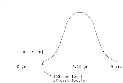
The worst case die/package combination for the example product line is a 100 wire package with the smallest die. The worst case die/package combination is based on the characterized worst case wire geometry and number of bonding wires. A post seal bond pull of 2 grams or less is considered unacceptable for 1.25 mil diameter aluminum wire. The proposed military standard requires a failure rate of no greater than 100 parts per million.
The distribution of bond pulls across devices is examined for each wire length. A statistical test is done for normality and in this example there is no reason to reject the assumption of normality. The worst case wire length in terms of variability and closeness to the specification of 2 grams is identified. The mean of this worst case distribution is found to be 4.26 grams with a standard deviation of .5 grams.
Thus, for this distribution the 2 gram specification is 4.52 standard deviations away [(4.26-2)/(.5)] and corresponds to a ppm level of approximately 3.1. If the distribution was to shift to the 100 ppm level such that 2 grams corresponds to 100 ppm (i.e., the 2 gram spec is now only 3.719 standard deviations below the mean), a shift of about .8 sigma [4.52-3.719] from the present bond pull mean of 4.26 would be required. This information is used to determine the number of devices needed for the capability study.
The following table can be used where the data is normally distributed:
| Sigma shift to 100 ppm level | Devices needed |
| 0.4 | 140 |
| 0.5 | 90 |
| 0.6 | 62 |
| 0.7 | 46 |
| 0.8 | 35 |
| 0.9 | 28 |
| 1.0 | 22 |
| 1.1 | 19 |
| 1.2 | 16 |
| 1.3 | 13 |
| 1.4 | 11 |
| 1.5 or greater | 10 |
n = [(Z_alpha + Z_beta)**2]/(d**2)
d = standard deviation shift = 0.8
alpha = 0.05 ; Z_alpha = -1.645
beta = 0.001 ; Z_beta = -3.09
[see Diamond, 1989, Practical Experiment Designs, pages 45-47]
Therefore, n = [(1.645 + 3.09)**2]/(.8)**2 = 22.42/.64 = 35. Thirty five devices are used in this capability study.
Using the standard bonding process, the 35 devices (each having 100 wires) are submitted to package seal, and post-seal bond strength measured.
For each wire position a mean and standard deviation is calculated across the 35 devices.
mean = xbar
standard deviation = sd
The distributions are evaluated and show no significant departure from normality.
The lower spec limit is determined: Here a lower bond pull of 2 grams.
For each wire position a “Z” is calculated:
Z = (xbar – LSL) / sd
For each wire position a probability of wire failure is determined by finding the probability of being below the Z value. Use of normal probability tables are utilized in this example because of the distributions being normally distributed. For this example there will be 100 values.
The probability of device failure is calculated by summing the 100 p values for failure of a wire position.
P(Device Failure) = Summation of P(failure of wire position)
= 0.00005 for this example or 50 parts per million
For this example it has been demonstrated that the probability of any device failing the minimum post-seal bond strength is less than 0.0001.