MIL-STD-883 method 2004.7 – Test condition B2: Lead fatigue
Purpose
This test is designed to check the resistance of the leads to metal fatigue.
Apparatus
Attaching devices, clamps, supports, or other suitable hardware necessary to apply a repeated bending stress through the specified bend angle.
Procedure
Each lead or terminal to be tested shall be subjected to a force as specified in 3.1 through 3.7, as applicable. Each lead shall be tested in the same direction through the specified arc in one direction and returned to the approximate original position. All arcs shall be made in the same plane without lead restriction. A test cycle shall be completed in 2 to 5 seconds. For devices with rectangular or ribbon leads, the plane of the arcs shall be perpendicular to the flat plane of the lead. The test shall not be applied to end leads of packages where its application will apply primarily torsion forces at the lead seal.
Direction of bends
Test leads shall be bent in the least rigid direction. If there is no least rigid direction, they may be bent in any direction. No lead shall be bent so as to interfere with another lead. If interference is unavoidable, the test lead shall be bent in the opposite direction to the angle specified and returned to its normal position.
Procedure for pre-formed leads
When normally straight leads are supplied in a pre-formed condition (including the staggered lead dual-in- line configuration), the lead forming operation shall be considered an acceptable lead fatigue test in place of that specified, provided the lead forming has been done after lead plating and the forming is at least as severe in permanent lead deformation as the specified bending.
Procedure for packages with Flexible leads
For flexible rectangular leads or round leads, the test force shall be 0.085kg ±0.009 kg (3oz ±0.3 ounces). Each lead shall be tested for three 90° ±5° arcs, unless otherwise specified.
Procedure for packages with Semi-flexible leads
For semi-flexible rectangle leads or round leads, the test force shall be 0.229kg ±0.014 kg (8oz ±0.5 ounces). Each lead shall be tested for three 90° ±5° arcs, unless otherwise specified.
Procedure for dual-in-line and pin grid array package leads.
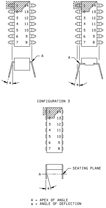
Dual-in-line (platform, side brazed, bathtub) package leads are leads normally aligned in parallel at a 90° angle from the bottom of the package during insertion. Dual-in-line package leads shall be bent three times inward through an angle sufficient to cause the lead to retain a permanent bend (i.e., after stress removal) of at least 15°. For configuration 1 and 2, the angle of bend shall be measured from the lead extremities to the first bend (see figure 2004-1), for configuration 3, the angle of bend shall be measured from the lead extremities to the seating plane (see figure 2004-1).
Pin grid array packages shall have the leads required for testing from the outside row of leads on opposite sides bent three times through an angle sufficient to cause the lead to retain a permanent bend (i.e., after stress removal) of at least 15°. The angle of bend shall be 15° from normal and the bend shall be made at the approximate seating plane. At the completion of the initial bend, the leads shall be returned to their approximate original position.
Optional procedure for Semi-Flexible and Flexible leads
As an option for all lead sizes, a force as determined by the following formula, unless otherwise specified, shall be applied to each lead to be tested for 90 degrees ±5 degree arcs of the device. All other conditions of section 3.3. and 3.4 shall apply. The test weight shall be calculated as follows: Weight = (area in square inches) x 2.1 % x (UTS in psi) x 453.6 grams/lb. Where UTS in psi is the ultimate tensile strength (UTS) for a particular material. Typical value for kovar, alloy 42 and copper materials are listed below. The UTS for other materials can be found in vendor data sheets. The result shall be rounded to the nearest whole number.
| Material | UTS in psi |
| Kovar | 75000 |
| Alloy 42 | 71000 |
| Copper 101 | 43,500 |
| Copper 110 | 31,900 |
Procedure for rigid leads or terminals
Testing of rigid leads or terminals is not required.
Failure criteria
When examined using magnification between 10X and 20X after removal of stress, any complete breakage (e.g. separation of the lead from the body) shall be considered a failure.
Summary
The following details shall be specified in the applicable acquisition document: