
During the SMTA International 2012 conference, Mr. Prof. Dr. Mathias Nowottnick presented the article Alternative Testing Methods for Electronic Assemblies (PDF) by Mathias Nowottnick and Andrej Novikov from the University of Rostock in Germany, Dirk Schade and Bob Sykes from xyztec.
Abstract
Electronic assemblies will be used more and more for harsh environments, e.g. for industrial application, avionic, environmental or automotive use. The common test methods can only give partial information about the demanded characteristics. This includes notably high or low service temperatures, corrosive atmospheres, vibrations or extreme acceleration. An accelerated ageing can be realized today by thermo-cyclic exposure, also in combination with other loading by high temperature or high humidity. In contrast it is usual to apply a shear test at room temperature and with shear rates in the middle range for testing and evaluation of mechanical properties of solder joints. A variation of the shear rate can deliver additional information. Extra slow testing velocities will effect solder creeping, but this needs also a very long testing time. In contrast very high testing velocities are reflective in an increased instantaneous strength, which is important for drop and collision demands. With a special developed impact test it is possible to identify better the characteristics of interfaces, voids or pre-existing damages by cracks. For some samples and defined conditions it is also possible to compare results of the impact test with standard shear tests. Further interesting approaches for alternative mechanical testing of solder properties for high and low temperatures will be also presented in this paper.
Introduction
The prediction of reliability of electronic assemblies will be realized usually by accelerated ageing tests in combination with statistical determination of failure rates. Typical week points are very often the solder joints, which could be degraded by thermo mechanical fatigue and finally fail. The determination of the end of life respectively of the remaining strength of solder joints occurs frequently by means of destructive testing. While the accelerated ageing is simulating the real environmental conditions like vibration, impacts, temperature changes, the destructive testing will be made usually at room temperature because of the practicability. In the same way the common shear tests will be executed only with medium shear rates of the tool. But the real deformations by creeping processes as a result of temperature changings will proceed with much slower speed. Other deformations by impacts or drops could happen much faster. The following investigations will show the influence of realistic conditions especially on the shear forces of solder joints and the technical possibilities for implementation for practical tests.
Influence of speed on shear force
The shear test of soldered electronic assemblies is defined by different standards, e.g. the IEC 62137-1-2 [IEC-07]. This standard prefers a speed for the shear tool in the range of 8.3 μm/s – 150 μm/s (0.5 mm/min – 9 mm/min). Most of the commercially available testing equipment is also configured for this speed range. Furthermore this standard recommends the shear test in combination with an accelerated ageing by temperature cycling. These temperature cycles are causing mechanical stress and creep deformation of solder joints because of the different coefficients of thermal expansion. Finally these creeping processes with alternating direction will lead to solder fatigue and failures. As creeping is a very slow deformation process, a dwell time of 30 minutes is needed for the assemblies in the temperature cycling test at least, so that relaxation and deformation can proceed completely. However the creep deformation rate is about three orders of magnitude slower than the recommended test speed of common shear tests.
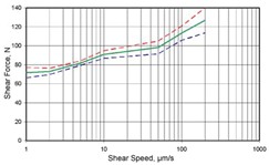
To identify the influence on shear result, the test speed was varied in the scope of possibilities of a common Condor 70 shear tester in the range of 1 μm/s to 200 μm/s. Using the example of chip resistors size 1206, the results of this investigation are visible in figure 1.
As expected, the shear force of solder joints will increase with rising test speed. However, the question arose, if this trend continues also for lower and higher speed. Therefore in the joint research project “NanoPAL” [WOL-09] a special shear tester was designed and tested, which allows to control the test speed down to 1 nm/s. Figure 2 shows the plot of load over time (blue curve) respectively the measured deformation (green curve).

Figure 2 – Results of a very slow speed creep test on a test board with 1206 chip resistors [WOL-09]
The testing takes place in this study with a constant load of 50 N and the resulting deformation rate was measured. For evaluation the average (linear) creep rate or the time until fracturing could be used. In this case a creep rate of 20 nm/s and a fracturing time after approximately 16 minutes was reached.
But it is also possible (and reasonable) to control contrariwise the creep rate and to measure the resulting shear force. In figure 3 are the test results as well as the simulated values for different models or data shown in the range between 2 nm/s and 1 μm/s. The diagram shows, that the test results are correlating fairly good with simulation. Therefore such measurements of solder joint creeping are very important especially for material science. But for the practical application such creeping tests with some minutes up to hours are likely to slow and not acceptable.
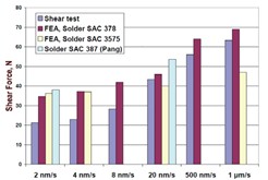
Figure 3 – Maximum shear forces [WOL-09] from test and simulation of soldered CR1206, creep law according to Schubert/Dudek [DUD-04] (SAC 378), Wiese/Roellig [WIE-04] (SAC 3575) and Pang [PAN-04] (SAC 387) for different creep rates
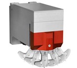
Very fast shear tests of solder joints are sometimes also of special interest for some stress situations. For automotive application, e.g. in the case of an accident, extremely (negative) accelerations are possible. Similar conditions could occur for mobile electronic devices for accidentally drop. For this purpose special drop tests are usual today, but these tests are delivering only qualitative effects and no quantitative results. A special designed probe for the shear tester Condor 70 makes the destructive high speed impact testing of soldered components possible. Therefore a pendulum with a defined mass and spring tension hits with a speed up to 4 m/s (9 mph) against the components. The impact could cause accelerations up to 10 g. A hardened bit is positioned at the end of the pendulum beside of the weight. Figure 4 shows the principle function and design of the impact probe.
A direct comparison of shear forces from impact test and a common shear test with a shear speed of 167 μm/s (1 cm/min) is visible in figure 5. Surprisingly the shear force is not rising with increasing test speed, which would be expected from the visible trend in figure 1. Furthermore it attracts attention, that the influence of the component size (0805, 1206 and 2512) and therewith also the section of the destroyed solder joint are much smaller than for a common shear test.
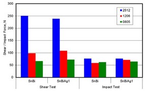
Figure 5 – Comparison of shear test results with 10 μm/s and high speed impact test results for different components and solder alloys
The reason for this changed fracture behaviors should be a different mechanism or location of fracturing. Already the observation of the impact procedure reveals, that after the impact test very often parts of the component or its metallization is remaining on the solder joint on the substrate side (see figure 6). Obviously the solder itself becomes stronger than base materials for the impact test procedure.
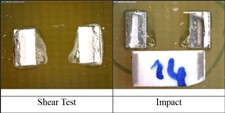
Figure 6 – Images of different fracture planes depending on the test speed
A specific view of the fracture planes in figure 7 shows very differentiated images depending on test speed. While slow shear tests are smearing over, voids and failures became more and more visible with increasing speed. But for the impact test the fracture planes appears rather coarse, which indicates more brittle fracture behaviors. Probably an incipient crack of the surface is sufficient for complete crack propagation through the structure of the solder joint. This could explain also that impact values for different component sizes are relatively closed together.
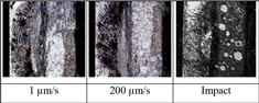
Figure 7 – Images of different fracture planes depending on the test speed
Further investigation with aged components will complete these results in the near future. Anyway the results are influencing the evaluation of reliability of solder joints in the field of mechanical high stressed electronic assemblies.
Influence of temperature on shear force
It is already known, that the temperature has an important influence on mechanical properties especially for solder alloys. The conventional trial for the measuring of material properties is a tensile test with “dog bone” samples, shown in figure 8.
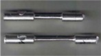
Figure 8 – Typical solder samples for tensile testing (before and after testing)
During the tensile test the samples will be extended with a constant rate until fracturing. The result of such material testing for a BiSnAg-solder is shown in figure 9 as an example.
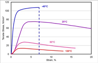
Figure 9 – Stress-strain diagrams of a BiSnAg2 solder alloy depending on temperature
Beside of room temperature (25°C) the test was conducted also for temperatures of -40°C, 90°C and 120°C. With increasing temperature the tensile strength is decreasing, which was also expected. Furthermore for the very low temperature the fracture happens already at 7% strain, whereas tests with higher temperatures also for 20% strain and more don’t break.
This influence of test temperature on mechanical properties of solder alloys should be also verifiable for the shear test of soldered components. For this investigation of temperature influence the shear tester Condor 70 was used again. It was equipped with devices for cooling and heating in the laboratory. Cooling was realized by a spray, which enables a temperature of -35°C. Heating was realized by convection with a hot gas nozzle, which enables in the first test run temperatures up to 75°C. The results for different temperatures and components sizes (0402, 0603, 0805, 1206 and 2512) are shown in diagrams in figures 10 and 11.
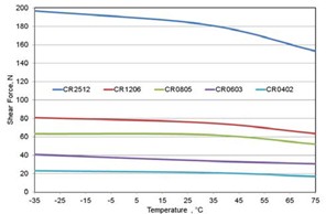
Figure 10 – Temperature dependent absolute shear forces for different chip components
The trend of decreasing shear strength with increasing temperature could be clearly confirmed. Also a considerable depression of curves over room temperature is visible.
To improve the comparability the interpretation of data was normalized by the shear force at room temperature for all components. Therefore all relative values in figure 10 are crossing at the value of “1.0”. In both directions from room temperature an increase or decrease of shear forces of +/- 20% could be expected in the considered temperature range. For future experimental work is an extended temperature range with improved devices intended.
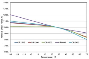
Figure 11 – Temperature dependent relative shear forces for different chip components
Further test developments and outlook
Beside of the investigation of the influence of ambient conditions on the prediction of reliability with destructive methods, the testing of quality with nondestructive methods should be also considered. Such tests are mainly functional test or in circuit tests, usual and reasonable for quality control after manufacturing of assemblies. It could be noticed that especially for advanced applications an increasing effort was made for testing, e.g. for automotive electronics.
An example is the temperature controlled function test for ABS/ESC-assemblies from automotive industry [MOE-12]. The heating of the PCB should simulate the natural heating of the appliance near the car engine up to the highest expected temperature with additional 10% safety (in sum about 120°C). Therefore the PCB runs through a heating system, where it must be tested as quickly as possible to avoid a significant cooling. A robot is used for handling from oven to the tester and the test handler itself is also heated. This heating is very important, because a usual functional test lasts about 1 minute, and in this time the PCB would cool down at least 30 K [MOE-12].
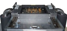
Figure 12 – Test adapter (lower part) in heated test handler – the tubes from the side transport the heated air [MOE-12]
This high-temperature functional test (HTT) as a 100% control of manufactured assemblies for about 120°C is a standard test since more than 10 years, especially for safety relevant components like brake controllers. Another new requirement is an additional low-temperature test (LTT) for -25°C, also as a 100% test. This test is applied for instance for radar sensors, which are located in the body of the car in the wing or underneath the bumper. The environment of this assembly area could be hot and cold. In opposite to the high-temperature test, the PCBs or assemblies should be “shock-frosted”. The feeding, loading and unloading of the fridge could be also realized by a robot in the lowtemperature test [MOE-12].
The biggest problem of this low-temperature test is the condensation. As soon as the part leaves the chiller and comes in contact with air at room temperature, water will condense on the surface instantly. Therefore this test is done only with closed control units today [MOE-12]. The experience in handling of high and low temperatures for functional tests can also influence the further development for destructive testing.
Acknowledgments
The authors would like to thank for the cooperation in the joint research project “Destructive and Nondestructive Testing of Characteristics of Nanoscaled Ageing Mechanism of Miniaturized Solder Joints – NanoPAL” and for the funding by the German Department of Education and Research. Furthermore we like to thank for support and many topical information by Rolf Moebus as a developer of test solutions from the company Baumann GmbH.
Click the icon below to view the PDF-file: Alternative Testing Methods for Electronic Assemblies


