Innovations in solar cell bond testing
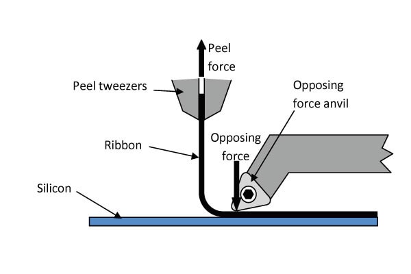
The mechanical and electrical quality of solar cell interconnection ribbon bonds is critical to optimizing photovoltaic manufacturing yield, energy conversion efficiency and product life expectancy. Bonds within polysilicon and thin film solar cells can be tested using a ribbon peel test protocol where the force required to peel, or break the bond is measured and the observed failure mode can be used to characterize the quality of the bond. Bond testing of solar cells is often difficult due to the fragile nature of the polysilicon or thin film substrates. The substrates are typically very thin and may have micro-cracks induced during metallization or solder reflow processing due to thermal mismatch during cooling. In order to successfully perform a ribbon peel test, an opposing force must be applied to the substrate. Simply providing an opposing force by clamping the polysilicon or thin film can result in breakage of the substrate rendering measurement of the bond strength as inconclusive. A new ribbon peel test protocol has been developed that avoids this problem by applying the opposing force directly through the ribbon resulting in highly accurate measurements.
By Dirk Schade, Director of Sales, XYZTEC BV, Panningen, The Netherlands
Introduction
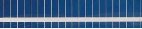
The manufacture of photovoltaic modules involves two primary interconnection processes. The first is the interconnection of individual photovoltaic cells referred to as stringing or tabbing, followed by photovoltaic module assembly commonly called bussing. During the stringing or tabbing process, individual cells are electrically interconnected using a pre-tinned copper ribbon with a typical width of 2.0mm. The solder coated ribbon is either dipped or sprayed with a liquid flux consisting of a chemical activator such as rosin or synthetic resin plus a solvent system in order to remove oxides from the surface of the ribbon and to promote wetting. The top layer of a solar cell is a transparent conductive oxide (TCO) to which solder will not adhere. Because of this a metallization paste is used to bond to the TCO and provide a solderable surface for the stringing or tabbing ribbon. A single point of contact between the collector grid and the ribbon is formed by either screen printing or jetting of metallization paste onto the substrate. Complete and uniform melting of the pre-tinned solder on the tabbing ribbon as well as the metallization paste is
essential in order to form a bond between the ribbon and substrate to channel electrical current from the entire solar array to a module junction box.
Following the stringing or tabbing process, individual photovoltaic cells are precisely mounted onto a glass substrate and attached in series forming columns. Typically six to ten rows of photovoltaic cells are bussed together using a 5.0 to 6.0mm wide copper bus ribbon to create a collector grid. Bussing of the columns of cells is performed by automated reflow soldering or manual soldering methods. The continual drive to reduce photovoltaic manufacturing costs is a driving force behind the reduction in polysilicon wafer and photovoltaic cell thickness. As a result the soldering process has become more challenging since these thinner cells are more susceptible to thermally induced micro-cracking.
During the soldering process a significant differential in the thermal coefficient of expansion (TCE) between the copper ribbon and polysilicon takes place when processing temperatures are greater than 300ºC and above. This differential applies stresses to the substrate which can result in the formation of micro-cracks that may not be detected during the manufacturing process and can result in a less than expected in-field product life span. The need for continuous process monitoring of time and temperature together with quality monitoring of the metallization paste and periodic solderability testing are critical to ensure the formation of high-quality interconnections throughout the assembly process.
Process Control and Defect Detection
Industry standards and production guidelines are presently under development that will address tabbing, stringing and glass-to-foil lamination to ensure solar cell product reliability. Dimensional criterion for tabbing ribbon are not yet standardized and are commonly as varied as the nomenclature used to describe them. For example, there are three basic specification sub-groups for tabbing ribbon including copper core specifications, finished material dimensions and solder coating specifications. The IPC’s Solar Standards Committee has standards under development in seven key areas. Principle among these is E-12 that will set acceptance standards for the lamination of glass-to-foil solar modules and E-14 providing standards for the tabbing and stringing of silicon solar cells.
In the meantime, testing of the quality of ribbon bonds continues as a critical necessity to assure that the mechanical and electrical integrity of solar cell interconnections is optimized to enhance photovoltaic manufacturing yield, energy conversion efficiency and product life expectancy. In order to successfully perform a ribbon peel test without breaking the substrate and rendering measurement of the bond strength inconclusive, a new ribbon peel test protocol has been developed that avoids this by applying the opposing force directly through the ribbon resulting in highly accurate measurements.
Using this new method, ribbon bonds within polysilicon and thin film solar cells can be tested and the force required to peel, or break the bond can be measured and the observed failure mode can be used to characterize the quality of the bond. The primary failure modes of solar cell bonds can be characterized as being either bond failure, under ribbon metallization failure or silicon failure.


Bond failures produce low peel force and low bond strength and generally result from non-wetting of the bonding process involving the ribbon and metallization paste. Under ribbon metallization failures produce a high peel force and are indicative of a successful ribbon-to-substrate bond. Silicon failures result from damage to the polysilicon substrate during manufacture and should be avoided. The preferred failure mode is an under ribbon metallization failure since this indicates that a reasonable bond strength has been characterized by the test.
Bond Strength Measurement
In addition to examination of the failure mode, force-displacement graphs are provided which shows the strength of each ribbon bond throughout the peel test enabling characterization and comparison between samples from various production batches.
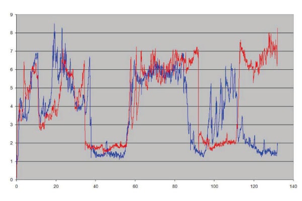
The precise measurement of force-displacement allows bond strength modeling to successfully predict the failure mode which can be used as an accurate prediction model of real life loading conditions.
Benefits of System Flexibility
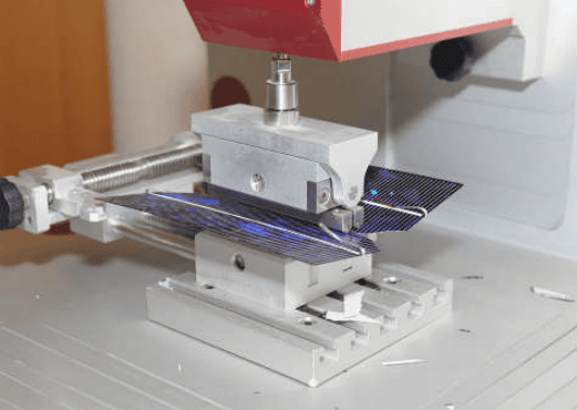
A significant advantage is that this new ribbon peel test protocol can be performed with a standard bond testing system equipped with a solar cell test module, USB tweezers and the appropriate measurement sensor.

This means that a single platform with multiple test capabilities provides the end-user with the added flexibility of performing many types of tests within one common system. In addition to ribbon peel testing of photovoltaic cells by using USB tweezers, a complete range of other testing applications such as bond testing, wire pull, ball shear, die shear, push testing and roller testing can be performed. All of these tests can be done with one test head that features four different measurement sensors. The system can perform mechanical shock testing by changing the test head for impact testing as well as high force impact measurement to determine the impact resistance of polysilicon or thin film substrates.
Adding to this versatility, the joysticks of the test instrument are ergonomically friendly and easily move the X-Y stage to the desired position, and feature 12 logically arranged buttons for increased operator efficiency. The all important software functions can be controlled by a single touch of a button to ensure simplicity of operation. The software features onboard graphics and intelligent wizards, providing intuitive operator control as well as sophisticated statistical process control (SPC) software thus ensuring complete documentation of the complete test protocol.
Conclusion
Tabbing and stringing of solar cells is a critical step that can make or break the photovoltaic module assembly process. The multiple soldering interconnection steps within the photovoltaic module assembly process play a vital role in throughput and conductivity, and critically impact in-use efficiency and longterm reliability. Precise measurement of ribbon peel force ensures adherence to high quality standards. Dirk Schade is Director of Sales for XYZTEC BV located in Panningen, The Netherlands. In his role he has gained worldwide recognition as an innovator in the field of bond testing equipment and has improved bond test methodology and solder joint integrity throughout the semiconductor and electronics assembly industries. He may be contacted at dirk.schade@xyztec.com.
About xyztec
Xyztec is a high technology based company, applying mechatronics, electronics, advanced precision mechanics and dedicated software to design innovative equipment that is used to control the quality of a wide range of industrial products. Our equipment is used worldwide throughout the semiconductor, automotive, solar and raw materials industries.
This article originally appeared in the July 2010 issue of Photonics magazine