How to Wire Pull (WP)
This manual is a guide advising what to consider and how to perform an optimal Wire Pull test. The focus of this manual is on wire- and ribbon pulls using wire hooks. However, we also cover Loop height measurement and briefly touch on topics like tweezer pull and peel testing of wires, which is the subject of a separate how-to by xyztec.
This extensive how-to consists of 11 paragraphs and 4 appendices. You can use the table of contents on the right to navigate between sections.
What is Wire Pull
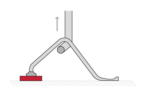
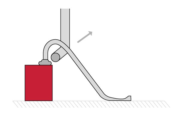
Wire pull testing applies an upward force under wires and effectively pulling the wire away from the substrate or die. The purpose of wire pull testing is to measure bond strength, evaluate bond failure modalities, or determine compliance with specified bond strength requirements.
A bondtester aligns a test tool under a wire or ribbon. Then, the Z-stage moves up until the bond breaks (destructive testing) or a pre-defined force limit are reached (non-destructive testing). Non-destructive test methods are typically for safety-critical, high-quality, and high-cost products, where operators must evaluate all wires without damaging the acceptable wires during a test.
Pull wires or ribbons by using a hook on a pull sensor or by cutting the wire or ribbon and pulling it with tweezers. The alignment of the test tool under the bond is essential to obtain reproducible measurements. Our semi-automatic or fully automatic Sigma testing system makes this easy and is compliant with international bond testing standards like DVS2811.
Type of wires to test
The cross-sectional shape of wires can be round or rectangular (ribbons). Thin wires are wires up to 75µm diameter (3 mil). Beyond that size, we speak about thick wire testing.
The material of the wires or ribbons is mostly gold, aluminum, copper, or silver. It is possible to test every type of wire or ribbon. Some wires or ribbons may be challenging to reach because of surrounding wires and components or low loop heights. We offer custom solutions and tooling to effectively pull test within the limits of even the most challenging applications.
Tool design
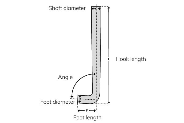
The most common tool to perform a wire pull test is a hook. Hooks come in many shapes and sizes. The angle is typically 85% to pull the wire into the hook and prevent hook slip during the test.
Standard hooks are made from bent round wire and have a specific foot diameter, foot length, and shaft diameter. The long hook length of 30 mm enables easy alignment and deep access to the test point where other components restrict access to your test site.
There is a wide range of standard bond testing tools available for various test types, such as:
- Pull
- Push
- Peel (wire hooks)
- Shear
- Scratch
- Measurement
Foot diameter
The hook diameter is an important consideration. The wire hook diameter should be around 3 times the wire diameter or ribbon thickness to reduce stress and avoid cutting the wire. The hook’s strength is similar to the maximum tensile load of the wire and ensures the highest load on the bond possible. The hook should not cut into the wire.
Foot length
The foot length should be about 3-3,5 times the hook diameter. Shorter lengths are available for fine pitch applications to avoid pulling multiple wires at once. Applications with larger distances between wires, or wires bonded in irregular patterns, are appropriate for longer foot lengths that provide more tolerance for any variability in wire position during manual and automated testing.
Wires or ribbons with extremely low loop heights (30 μm or less) may require special tooling to get underneath. Where regular hooks are too thick, a flat wire hook may fit. Alternatively, USB Tweezers with a pre-defined closing distance and/or grip force are suitable for low loop heights and to pull cut wires.
Tool quality
Material and damage
The material of the tool should have sufficient strength to withstand the maximum pull force. Tungsten steel is an appropriate material because it is easy to manufacture to the desire shape and accuracy. In addition, the sample material is typically softer than the tool itself, so tool wear is rarely a problem.
Poor tool quality usually is due to damage. The most common causes of damage are being hit by the sample or work holder when changing the test sample. Never use a damaged tool because it will affect the measurement results.
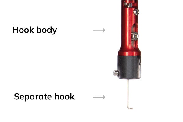
A wire hook assembly comes in 2 pieces to set hook concentricity and minimize recovery time in the event of hook damage from a collision.
Hook concentricity
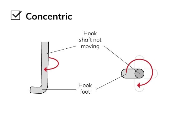
What is a concentric hook?
A concentric hook is where the middle of the hook (tool-position) remains fixed during tool rotations. Hook concentricity is essential for performing automation, and it makes manual alignment easier.
The tool position is not perfectly concentric and may describe a circular pattern while rotating the tool. The tool eccentricity indicates an offset between a perfectly aligned tool and the actual positions when rotating. In some fine-pitch cases, further concentricity correction may be necessary. Software correction can compensate for this offset and correct the concentricity to ensure the tool position meets the center when a tool rotates.
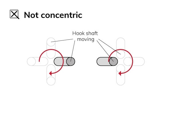
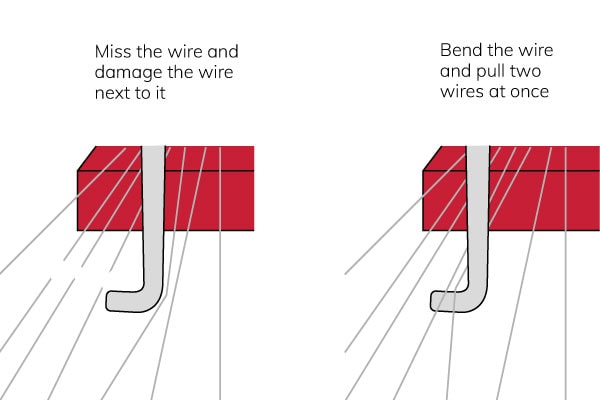
Non-concentric hook problems
If the hook does not rotate concentrically, it can damage other wires. First, the hook goes below the wires and is ready to rotate. Then, depending on the type of eccentricity, it will miss the wire and damage the wire next to it or bend the wire and test two wires at once.
Concentric hooks
There are 3 ways to adjust the concentricity to ensure the hook can achieve optimal rotation performance:
- Manual alignment
- Imprints using soft clay
- Automated correction with computer vision
Mechanical adjustment is an effective and common way to fix wire hook concentricity. However, only with software correction it is possible to achieve a hook concentricity within 5 µm.
Tool alignment
The position of the hook should be underneath the wire without touching any other wire or part of the sample. It is necessary to null the sensor (force zeroing) before taking the measurement.
Rapidly test multiple wires
With the ‘auto-hook’ function in the Sigma software, it is possible to automatically align the hook under a wire without disturbing the wires next to it. Auto hook rotates the hook according to operator-defined rules before a test begins. This function is beneficial and essential for all wire pull testing and requires a concentric hook.
Operators must enable ‘auto-hook’ and start a test. Then, the Sigma bond tester automatically follows the steps:
- Move down between the wires
- Rotate the hook under the wire
- Optionally perform a ‘hook shift’ movement towards or away from the wire
- Perform the wire pull test
- Reverse these steps and go back to the start position safely
Along the wire or across the wire
It is possible to start with the hook along the wire or across the wire. The latter case needs extra rotations before and after the test.
Auto hook along the wire is faster than across the wire because the hook rotates 2 times rather than 4 times. Starting across the wire makes it possible to see the hook engage with the wire when below it.
Make alignment easier and minimize Z movements by testing away from the previous test and aligning the hook low and close to the next wire to test.
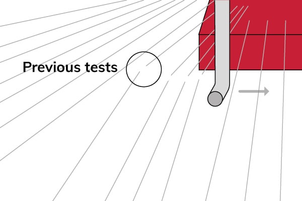
Where to pull?
A common practice is to pull at the center of the wire length. The MIL standard 2011 specifies pulling between mid-span and loop apex to avoid adverse wire deformation, but previous versions of the same standard set pulling mid-span.
Test close to the bond when only one of the two bonds is of interest. Rise the bond’s load and increase its chance of a bond failure. For example, when the failure mode of interest is the first bond, try to align the wire hook close to the first bond. It is crucial to pull in the same place. Otherwise, it will increase the test force distribution and affect the failure modes.
Automation ensures consistent tool alignment. Only highly advanced automatic bond testers can achieve the most reliable results to optimize the process.
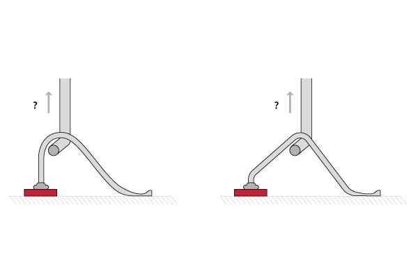
Alignment along the wire and the wire length affect the angle of the wire pull. The angle changes the load on the bonds.
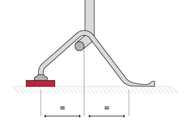
Standard DVS 2811 advises that the pull position should be such that the angle of the wire at the first and second bonds are equal. It then normalizes the results around a “standard” angle of 30° using a correction factor.
Multiply the measured pull force by the correction factor to calculate the load on the bonds. Then, compare the strengths of different wire bonds with a variety of pull angles with DVS 2811.
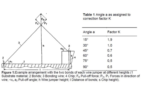
Triangulation
While DVS 2811 sets the angles equal and therefore the forces too, it is possible to pull in many positions and create different forces on the first and second bonds.
Appendix 1 of this how-to has various formulas to calculate the forces by triangulation. An advanced bond tester can calculate these values.
Automation and wire detect
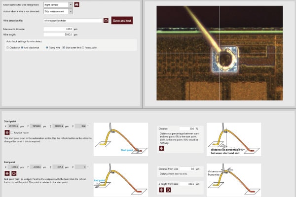
Automation eliminates the influence of operators on the measurement results. Highly advanced bond testers, like a Sigma, can perform automatic tests by running automation programs that may include fiducial mark recognition. Automation pulls all wires in a very consistent position, so the distribution of results goes down, and the quality of measurement data goes up.
A Sigma bond tester optically detects the wire and corrects for “wire sweep” before pulling the wire automatically. Wire detection ensures more repeatable positioning even when the placement of wires is not consistent. By measuring changes in the wire position, the bond tester can correct the test position and ensure consistent results.
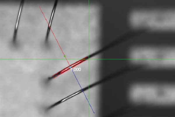
At the location of the green crosshairs, the illustration shows how the hook is driven to a corrected position after the bond tester detects the wire. When the bond tester performs the pull test, it does not miss the wire but pulls it in the same position as every other wire.
Automatic wire detection enables a higher degree of consistency over what is possible when testing manually.
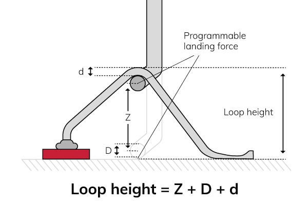
Loop height measurement
Loop height measurement is necessary to make the force calculations. Bond testers traditionally measure forces, but the system can measure distances with the same wire pull sensors. Advanced Sigma bond testers can even combine the measurement of loop heights with the wire pull test.
The hook lands on the substrate with a programmable force to measure the loop height.
Work holder and clamping
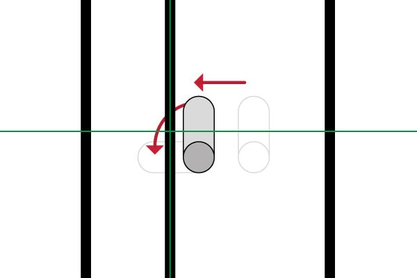
Perfect sample clamping is essential to keep the sample locked in position. Without firmly and rigidly clamping, the test time increases, displacement data is wrong, and test data becomes less reliable.
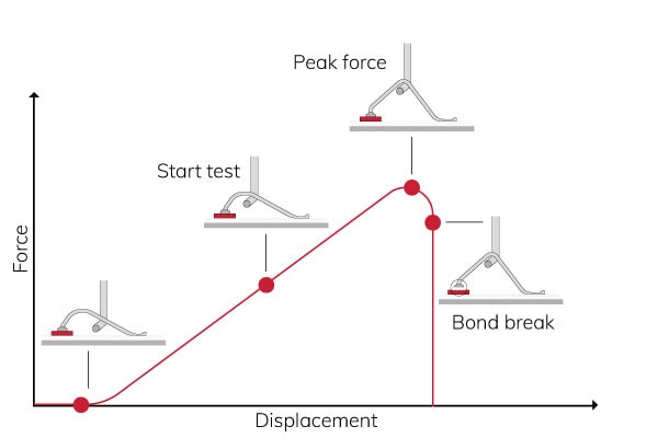
This image shows the best measurement. The sample is clamped to the base, which gives accurate measurements.
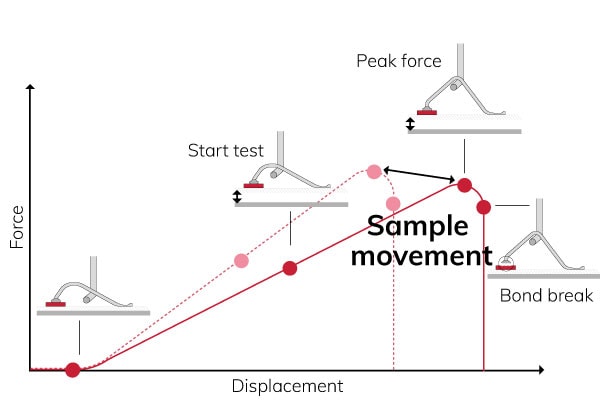
In the image above, the sample is not clamped. The sample moves, hence,
- Sample movement results in longer test time and displacement
- If the test time is longer, the true test speed is slower
- Different test speeds give different peak forces
- Variable clamping increases error and distribution
Variants on wire pull
Vector pull
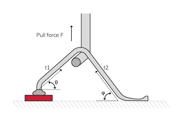
Vector pull is a variant of wire pull where the hook moves at a programmable angle instead of moving up at a 90° angle relative to the sample. This enables different loading conditions between the first and second bonds that can help to promote the failure mode of interest. A bond tester can achieve this by simultaneously moving the X- and/or Y-axes with the Z-axis.
Alternatively, it is possible to clamp the sample in an inclined work holder. See an example of this under SMD gull wing leads testing.
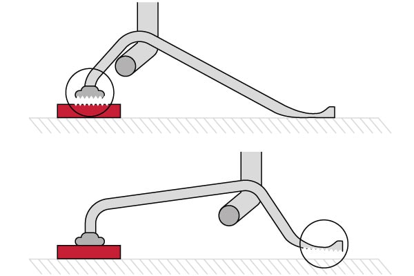
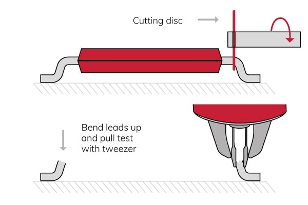
SMD gull wing leads
The best way to test the bond of an SMD gull wing lead is to cut the body from the leads and then test each lead with a tweezer pull sensor. Cutting the bond enables bond testing without effect from the body and the other leads.
This involves some preparation time. Pull testing without cutting the body off and use a hook, can cause problems:
- There is very little space to get the hook in to pull a lead.
- The body supports the lead being tested.
- When the hook is a tight fit under the lead, in the test method, the sensor must not be nulled/zeroed before the test; it must be manually nulled before the alignment.
If the hook is closer to the package than the pad, the test load goes into the package rather than the bond of interest. However, a weak lead-to-pad bond will still give a lower result. The failure mode analysis of the tested bond shows poor soldering.
Use vector pull with a special hook to minimize the body’s effect on the bond. Be aware of clearance issues when designing a test method.
Vector pull applies a higher test load to the bond pad than regular wire pull.
Vector pull loads the bond of interest with a higher force. Analysis of the results may still provide meaningful data on the bond of interest, despite the test load fraction going into the package.
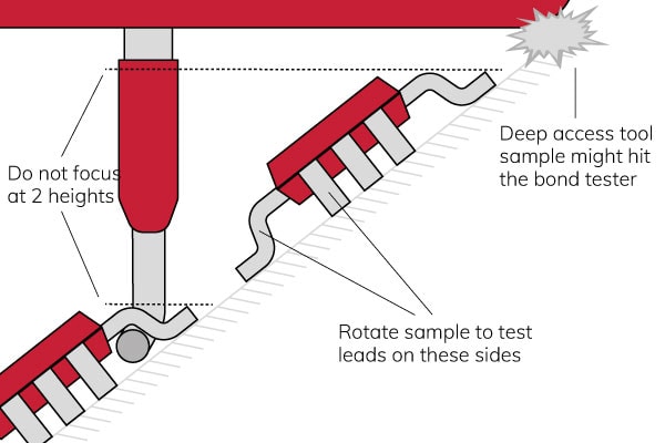
Incline the test sample
Another method to test SMD gull wing leads is to incline the sample and use a regular pull sensor with a strong wire hook. However, this method comes with some limitations.
- Large samples can hit the bond tester head or frame. However, there are large work area bondtesters available to avoid this.
- Focusing a microscope at different test heights may not be possible or can reduce the number of tests per hour. The Sigma’s EZ microscope support helps to overcome this.
- It is necessary to rotate the sample to test all sides of the component.
- Handling and clamping an inclined sample can be difficult.
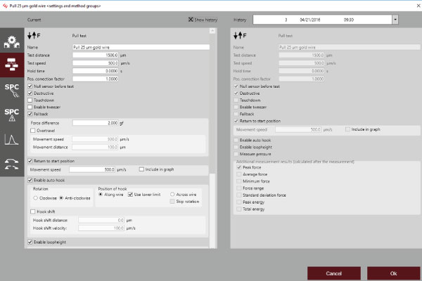
Test method settings
Test definition
The test method allows programming the test variables. The basic test settings contain:
- Test distance
- Test speed
- Destructive or non-destructive test.
There are many more settings. It is possible to combine all settings in extraordinary ways to solve all challenges in a smart way.
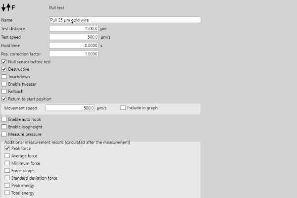
Hold time
The hold time is most relevant for non-destructive tests.
Null sensor before test
It is optional to null the sensor before almost every test type.
Touchdown
Using tweezers, a touchdown is necessary before the test. In the case of pull, it is defined by a landing force, maximum landing distance, and a landing speed.
Fall back
When defining a fallback to determine the end of the test, the force difference is the most relevant value to set.
Overtravel
The bond tester also gives the option to “overtravel” a distance after fallback is triggered. This clears the pulled wire away from the test area for failure mode analysis.
Autohook and loop height
Pull testing can be performed with or without auto-hook rotation and may be combined with loop height measurements before the pull test.
Remember test settings
Sigma bond testers automatically store test method settings in one place to track method changes over time. Easily request previous test method settings behind a ‘show history’ checkbox.
Statistical Process Control (SPC)
Like all other test methods such as push, peel, shear, and probe, it is possible to set SPC warnings for the pull method. Depending on the measurement result, each measurement can include a warning or a failure to force operators to enter a remark. The software can even lock the tester until an engineer checks the results and releases the tester to continue.
The test method settings include a spectrum of statistical values. Everything shown is crucial for most quality assurance processes, from a simple mean or median calculation to Cpk values and lower and upper spec limits.
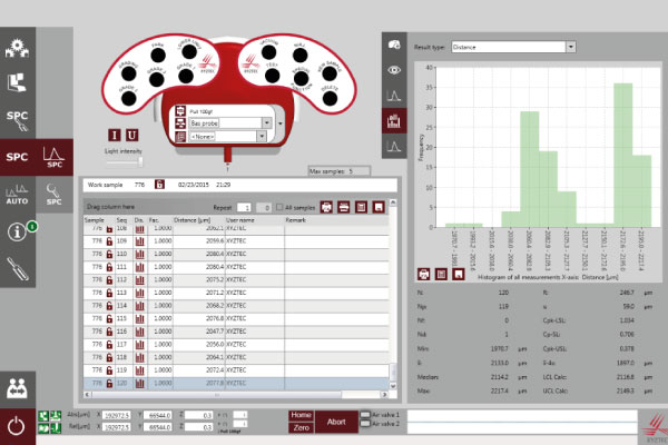
Data analysis
Making the right decision on the test results may require additional analysis. Sigma bond testers assist data analysis by storing pictures and/or videos of before, during, and after the test with the measurement data and grading information.
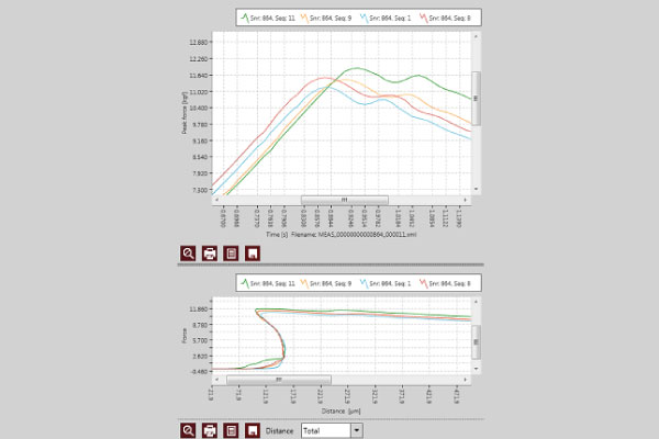
The Sigma software comes with a sophisticated query screen that allows the engineer to sift through massive quantities of test data. Overlay the force or hysteresis graphs for numerous measurements to compare the graphs from multiple measurements. Forms offer an auto filter feature that will only show the measurements and samples for a specific field value or set of field values. The engineer has control over data recall and sorting in the SPC query screen.
For strict data collection, an auto print feature automatically prints selected reports for a dataset as a PDF file when reaching a certain number of samples.
Data export
Sigma bond testers can export standard reports in many common file formats (i.e., XLS, DOC, PPT, PDF, XPS, CSV, XML, DBF, etc.) to export data to external systems.
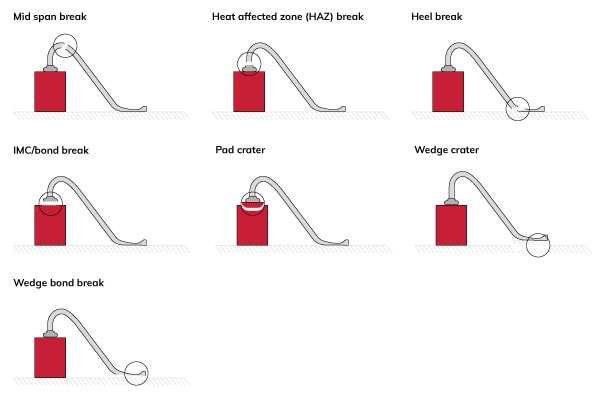
Failure modes
MIL-STD-883 2011.9 lists 26 failure modes (failure categories) depending on the type of sample. Below is an overview of the most common failure modes for gold wire and aluminum wire. It is also possible to download the result codes in our grading library.
Gold wire failure modes
Mid span break
- Bond strength unknown
- Acceptability depends on measured force
Heat affected zone (HAZ) break
- HAZ strength known
- Acceptability depends on measured force
Heel break
- Heel strength known
- Acceptability depends on measured force
IMC/bond break
- IMC/bond strength known
- Acceptability depends on measured force
Pad crater
- Pad strength known
- Acceptability depends on measured force
- Possibly bonder process problem
Wedge crater
- Acceptability depends on measured force
- Possibly bonder process problem
Wedge bond break
- Wedge bond strength known
- Acceptability depends on measured force
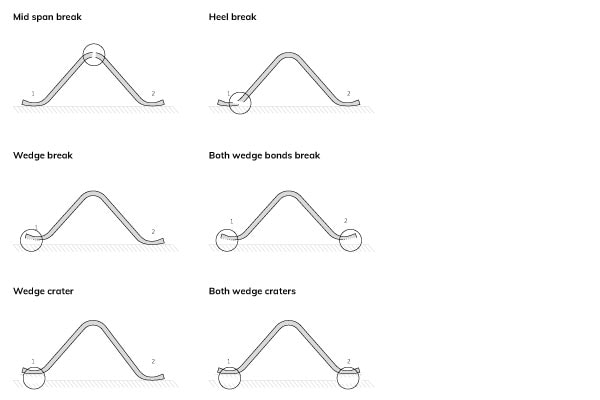
Aluminium wire failure modes
Mid span break
- Bond strength unknown
- Acceptability depends on measured force
Heel break
- Heel strength known
- Acceptability depends on measured force
Wedge break
- Wedge bond strength known
- Acceptability depends on measured force
Both wedge bonds break
- Possibly weak bonds
Wedge crater
- Acceptability depends on measured force
- Possibly bonder process problem
Both wedge craters
- Probably weak bonds
- Possibly bonder process problem
Sigma bond tester
A Sigma bond tester is the most advanced bondtester for wire pull. It comes with game-changing automation capabilities and high specifications in:
- Sensor accuracy and resolution
- Large X stage
- Superior axis speed
- Cameras and illumination
- Future proof and modular design
Contact us and challenge us to customize a bond tester to solve your quality control processes.
Appendices
This how-to has four appendices, namely:
