How to: Shear
This manual advises what to consider and how to perform an optimal shear test. The guide touches topics on shear tool design, tool quality, tool alignment, and how to hold the sample. We share common failure modes for gold balls, copper balls, solder balls, die shear, and wedges. The guide also covers cavity, passivation, zone, vector, and SMT lead shear.
This extensive how-to consists of 18 paragraphs. You can use the table of contents on the right to navigate between sections.
What is shear testing?
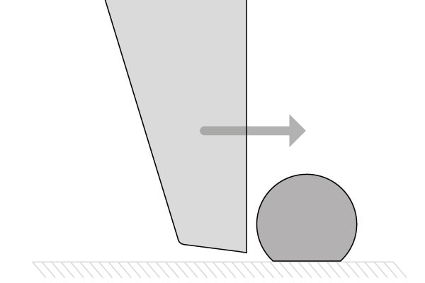
Performing a shear test, a bond tester applies a lateral load to the sample and shears the bond from its surface.
Types of shear tests
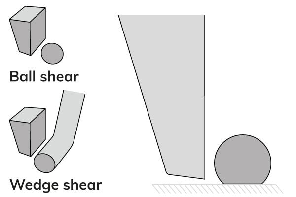
There are many types of shear tests. The most typical test types are:
There are also shear tests for less common applications, like: cavity shear, overhanging die shear, passivation shear, ribbon shear, zone (total ball) shear, thin die/high force shear, vector shear, and SMT gull wing leads shear.
Shear tool design
Some fundamental considerations apply to all shear tool design applications.
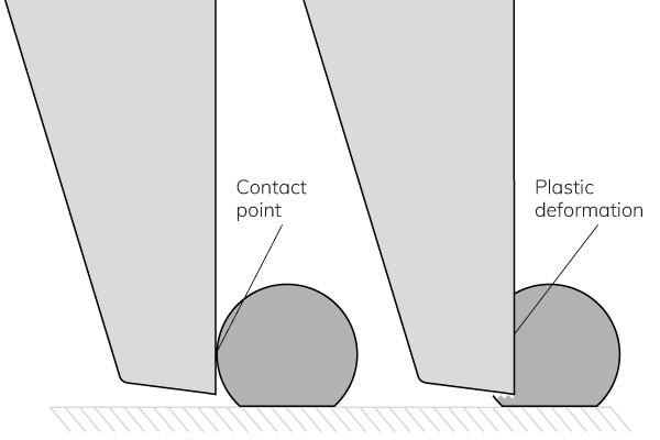
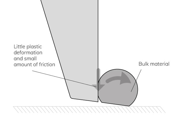
An initial point or line contact occurs when the tool contacts the bond. As the test continues, this results in high local stress at the contact and plastic deformation in the sample. Below is a typical plastic deformation at the maximum possible test force.
Down thrust
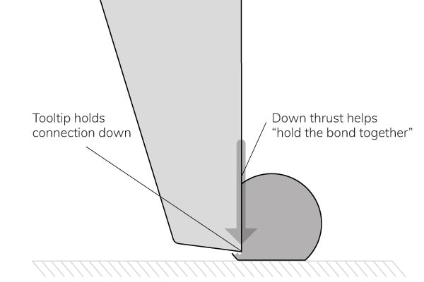
For the bond to fail, the ball must be able to lift up from the bond, but the tool is physically holding it down. To make it even less likely to get a bond failure, the plastic deformation produces a down thrust that pushes the bond together, helping to support it. Down thrusts vary from nothing in hard samples up to 40% of the test load in composite interconnects. In most cases, it is around 10% of the test load.
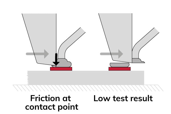
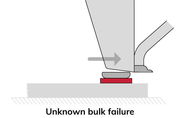
Hard bulk material
For hard bulk material, there is no down thrust. Only the friction between the tool and the ball at the contact point supports the bond. This makes it possible for the ball to rotate and to make a bond failure. The deformation (strain rate) is faster at high test speeds. The bulk material hardness increases with the strain rate. So, at high speed, the bulk material is harder and can therewith create more failure modes of interest.
Tool rake and clearance angle
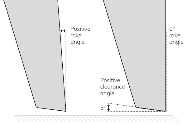
The rake and clearance are essential angles of the tool surfaces that contact the interconnect. For example, a standard shear tool should have a 0° rake angle and a positive clearance angle of around 5°.
Zero rake angle
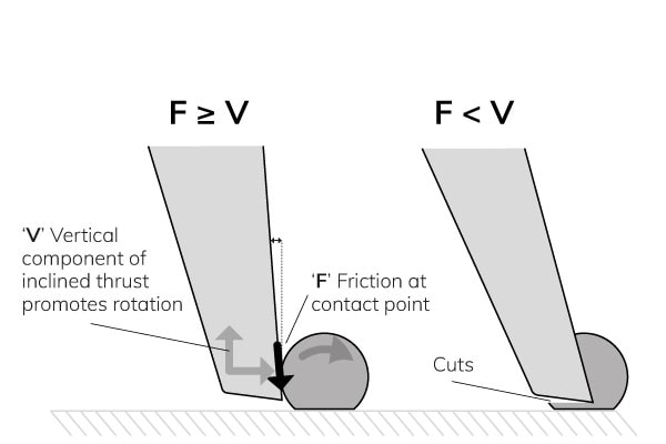
A zero-angle rake is optimum. A positive rake angle might promote rotation and induce bond failures. In reality, the friction at the contact point negates the vertical lift component of the inclined trust unless the rake angle is steep. A steep rake angle cuts the bulk material like a knife, resulting in low test forces and bulk material shear.
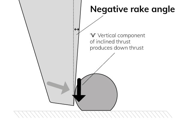
A negative rake produces down thrust, supporting the bond, and has no benefit.
Clearance angle
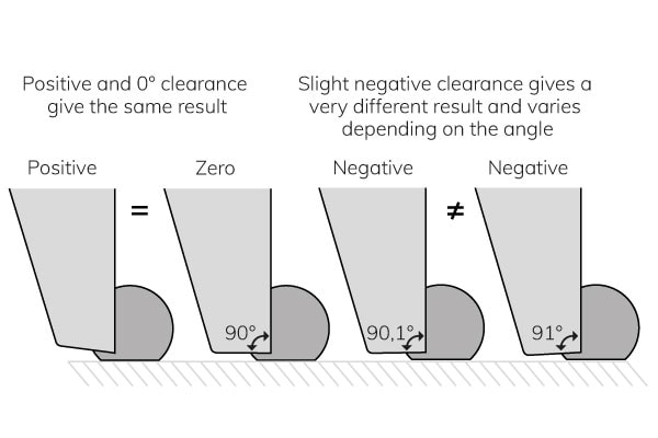
A negative clearance angle produces an undesirable down thrust that supports the bond. A negative angle would also influence the shear height, as the back side of the tool would touch the surface first. A positive angle does not show these issues. Any positive angle has the same result since the face of the tool has no interaction with the bulk material. The only downside of a large clearance angle is faster tool tip wear and a weaker tool tip.
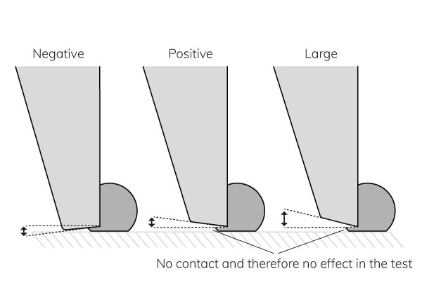
Never have a 0° clearance angle. Due to manufacturing tolerances, it may become negative, and the difference in test results and failure mode between a slightly negative or positive clearance is significant.
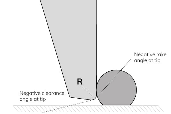
Effect of tool tip radius
A tool tip radius has the effect of negative rake and clearance. A negative rake and a negative clearance are unacceptable. So, the tooltip must be a knife edge.
Every edge has a manufacturing tolerance, so what tip radius is effectively a knife edge? First, find the required degree of sharpness by testing with a range of tip radii. Different radii will produce different results until the tip is sufficiently sharp that further reduction in its radius makes negligible or no difference. Then specify the tip radius as less than this amount.
| RADIUS R | TEST FORCE | BOND FAILURE |
| 40 µm | 110g | 0% |
| 20 µm | 106g | 0% |
| 10 µm | 102g | 1% |
| 5 µm | 100g | 2% |
| 2 µm | 100g | 2% |
| 1 µm | 100g | 2% |
In this table, the required sharpness is between 10 µm and 5 µm. This is when no further reduction makes a difference.
A sharp tip is easy to make with a good grinding process. A good grinding process will produce a sufficiently sharp edge for virtually any application.
Tool material
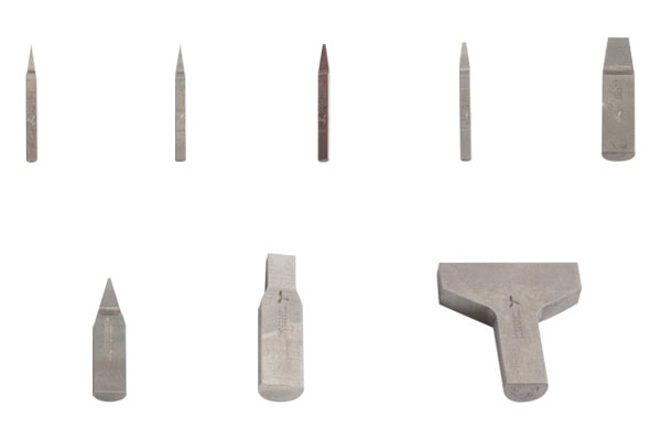
Shear tools are suitable for many different applications and soft or hard samples. A wide range of standard shear testing tools are available for many different applications. Besides the standard tools, it is possible to develop custom solutions to fulfill all test requirements.
Material
Shear tools are made from hardened tool steel or tungsten carbide.
- Hardened tool steel is hard and tough and typically ideal for high-force applications.
- Tungsten carbide is extremely hard to resist wear but is brittle and can have a very sharp tip for small geometries.
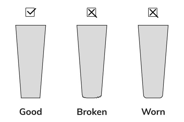
Tool quality
Poor tool quality usually is due to damage and is unlikely to work correctly. The most common causes of damage are being hit by the sample or work holder when changing the test sample. Do not use tools with damaged or worn edges, because it will affect the measurement results.
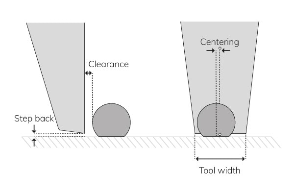
Tool alignment
There are 4 alignment factors:
- Tool width; part of the machine setup
- Centering; set by the operator
- Clearance; set by the operator
- Step back; to program by the operator but set by the machine
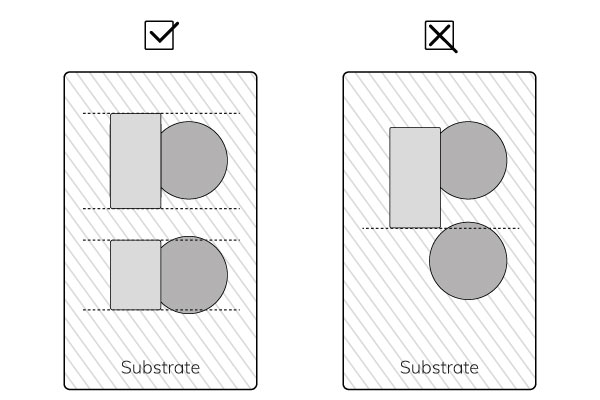
Tool width and centering
The minimum tool width is the same as the sample deformation but requires perfect alignment. Therefore, it is better to use a slightly wider tool than the target.
The bond pitch also affects the optimum tool width. In the case of a large pitch, it is possible to use a wider tool than fine pitches. Make sure the tool cannot hit the next bond.
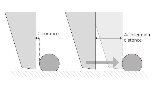
Clearance
The clearance usually is small, and its precise amount is not important. However, it is crucial when testing at high speed, and a large acceleration distance is required to reach the test speed.
A Sigma bond tester can accelerate to 5 mm/s in a few µm, but consider the clearance alignment above this test speed.
Step back
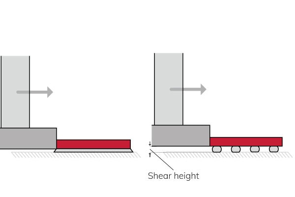
Step back defines the resulting shear height.
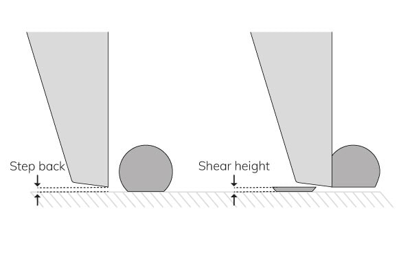
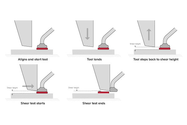
Shear height
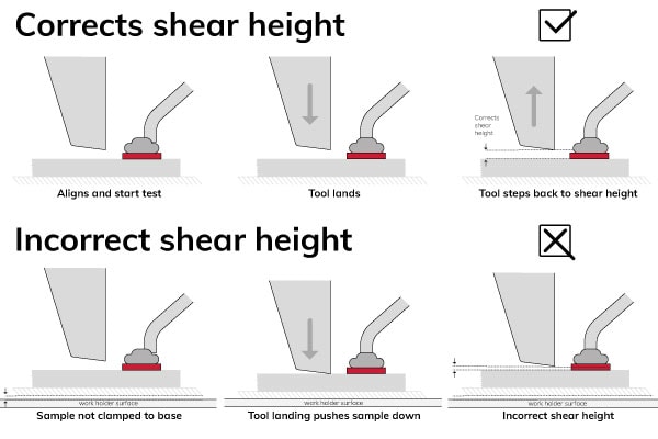
It is easy to set the shear height by programming the step back:
- The operator aligns and starts the test.
- The tool lands. Some machines have a programmable landing force.
- The tool steps back to the programmed shear height (step back), and the shear test starts.

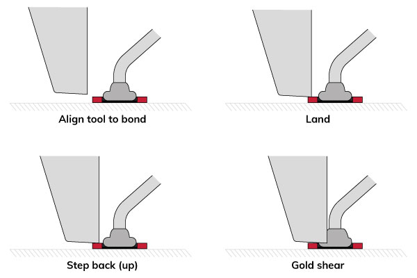
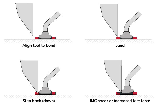
The best shear height is the one that produces the most failure modes of interest and the highest test force. The lowest shear height often produces more failure modes of interest and the highest force. A high shear height often has no failure modes of interest and a low test force.
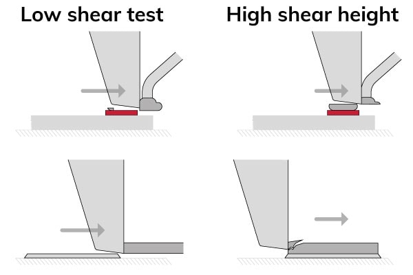
Suggestions are that high shear height promotes a bending moment resulting in more bond failures.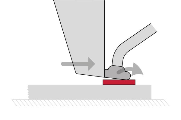
Usually, friction at the contact surface stops the ball from rotating, or the ball is shared with a lower test result and not the highest test force possible.
Holding the sample
Shear height
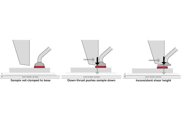
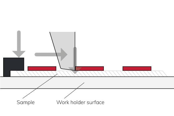
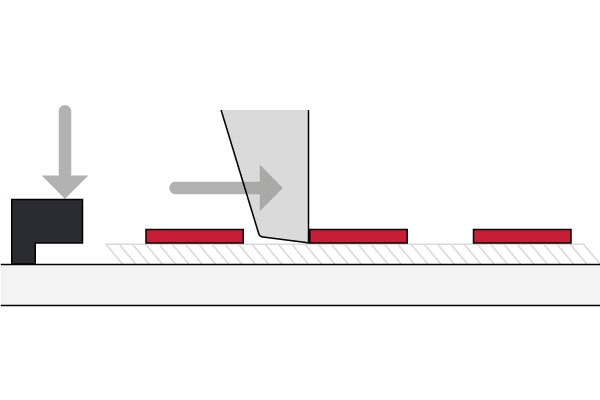
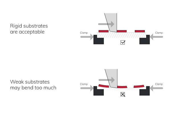
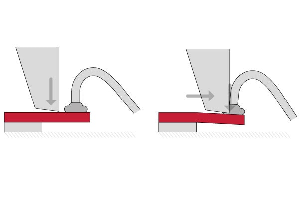
For most shear tests, clamping the sample firmly down to a rigid surface on the work holder is important. If the sample is not properly clamped down to the work holder base, the tool landing pushes the sample down, giving an incorrect shear height.
Poor sample clamping results in an inconsistent shear height. The shear test starts with the sample floating above the work holder. During the test, a down thrust pushes the sample down. This results in an inconsistent shear height.
Sample clamping
There are 5 primary ways to hold the sample:
- Leading edge
- Central
- Trailing edge
- Side clamps
- Vacuum
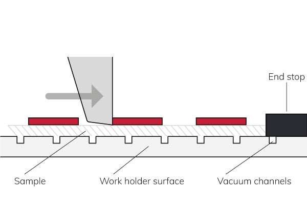
Leading edge
Leading edge is the simplest way to hold the sample because the down thrust holds the sample down, and because of the end stop, the sample cannot move. Work holders are flexible, and one work holder can handle a range of sample types and sizes.
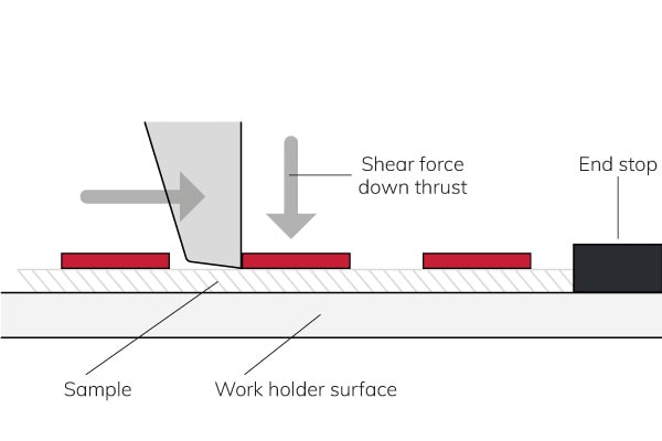
However, compressive stress between the shear tool and the end stop can cause the sample to buckle.

Central
Holding the sample central typically has the most disadvantages. It limits access, and the tool cannot go to the center. Besides, the sample may buckle, or the sample may slip.


Trailing edge
Holding the sample with a trailing edge has many advantages, like:
- The sample cannot buckle
- The down thrust holds the sample in good contact with the work holder
However, the sample can slip out of the clamp. Another disadvantage is that trailing edge limits the maximum shear force to the clamp slip resistance.
Side clamps
Side clamps are very flexible. One set of side clamps (in a vice construction) can hold many different sample sizes and types.

Its disadvantage is that there is nothing to support the sample in the vertical axis, thereby controlling the shear height.
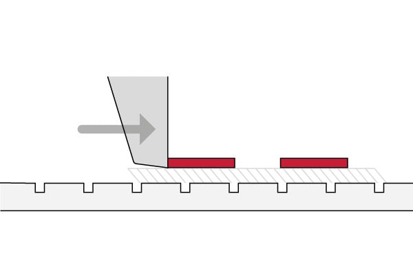
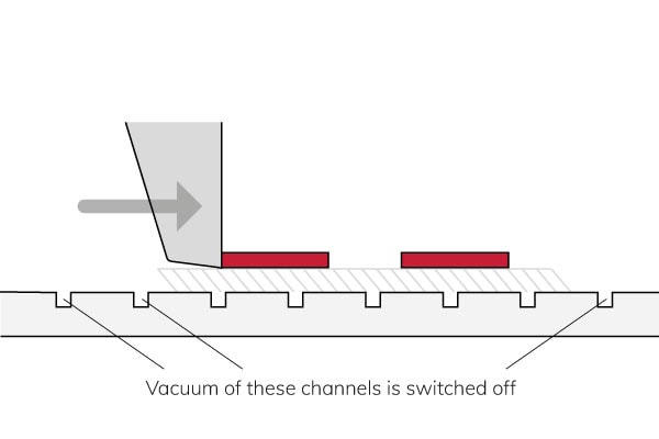
Vacuum
Holding the sample with vacuum is flexible and holds the sample down very well. There is no vacuum in the vacuum channels around the sample. However, the sample may slip.
The disadvantage is that the vacuum slip resistance limits the maximum shear force
Clamping combinations
It is also possible to combine these ways to hold the sample to increase the holding force and benefit from more than one holding method. A common example is a leading end stop and vacuum.
Failure modes
This capture lists the most common failure modes for
- Gold and copper ball shear
- Solder ball or bump shear
- Die shear
- Wedge shear
These failure modes use a basic shear test where the principal test method variables are the shear height and the test speed.
The failure mode of interest is the bond failure in the intermetallic layer between the bulk wire material and the pad or the die bond. Problems with the bond quality are due to incorrect bonding processes, material quality, or bond aging.
It is also possible to download the result codes from our grading library.
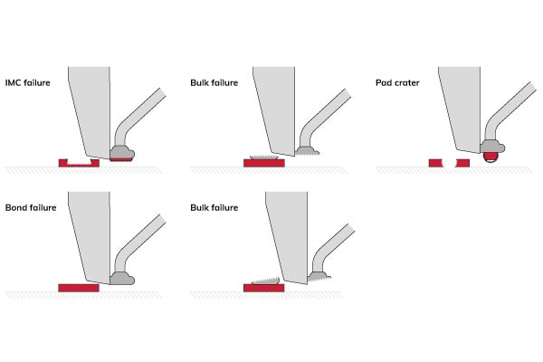
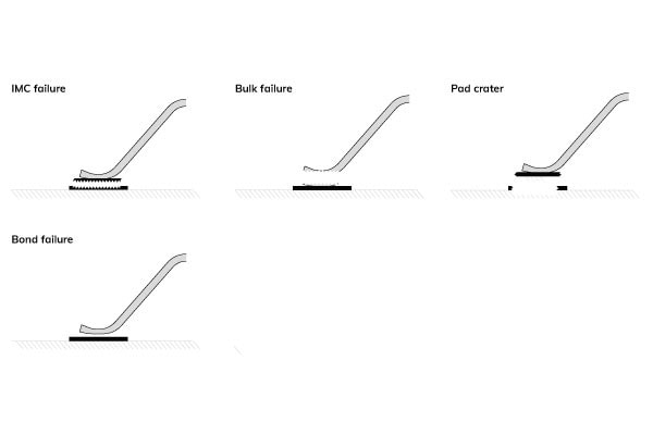
Gold and copper ball
Failure in IMC
- Bond strength known
- Acceptability depends on the strength
Failure in bulk material
- Bond strength not known
- Acceptability depends on the strength
- Bond strength good or bond test bad
Pad crater
- Pad strength known
- Acceptability depends on the strength
- Possibly bonder process problem
Bond failure
- Bond strength known
- Acceptability depends on the strength
- Probably very weak bond
Failure in bulk material with inconsistent shear height
- Bond strength not known
- Bad test, poor sample clamping, or bond tester problem
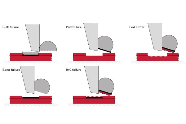
Solder ball or solder bump
Failure in bulk material
- Bond strength not known
Pad failure
- Bond strength known
- Acceptability depends on the strength
Pad crater
- Pad strength known
- Acceptability depends on the strength
Bond failure
- Bond strength known
- Acceptability depends on the strength
- Probably weak bond
Failure in IMC
-
- Bond strength known
- Acceptability depends on the strength
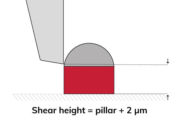
Solder ball and copper pillar
Shear high on copper to test the bond substrate or shear the solder to test the bond. It is probably a non-wet failure.
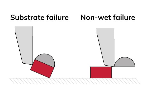
The shear height must be greater than the pillar to shear the solder. Therefore, the optimal shear height is the height of the pillar + 2 µm.
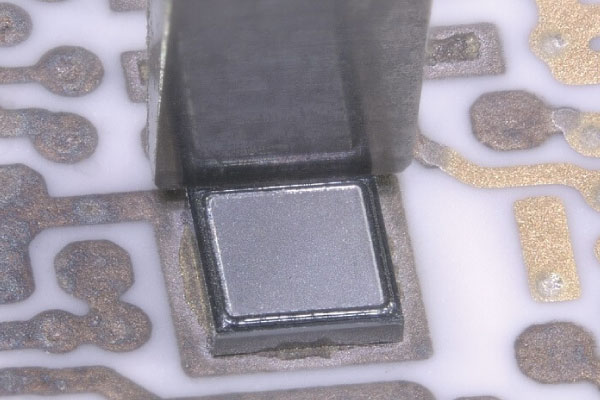
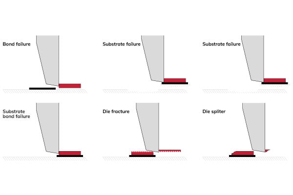
Die shear
Die bond failure
- Bond strength known
- Acceptability depends on the strength
- Probably weak bond
Substrate failure
- Bond strength known
- Acceptability depends on the strength
Bond failure
- Bond strength known
- Acceptability depends on the strength
Substrate bond failure
- Bond strength known
- Acceptability depends on the strength
- Probably weak bond
Die fracture
- Bond strength not known
- Die strength known
- Acceptability depends on the strength
Die splinter
- Bond strength not known
- Acceptability depends on the strength
- Bad test or maximum test force possible
Wedge

Failure in IMC
- Bond strength known
- Acceptability depends on the strength
Failure in bulk material
- Bond strength not known
- Bond strength good or bond test bad
Pad crater
- Pad strength known
- Acceptability depends on the strength
- Possibly bonder process problem
Bond failure
- Bond strength known
- Acceptability depends on the strength
- Probably very weak bond
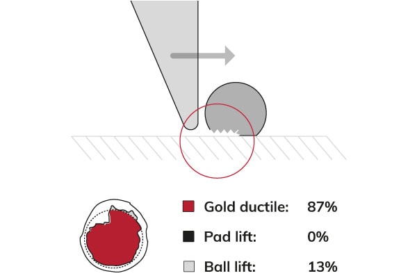
Failure mode analysis
Optical inspection helps to perform image measurements or to identify the failure modes of the captured test results. For ball shear and wire pull, smart optical inspection algorithms calculate the percentage of the remaining bond material in the region of interest and identify the failure mode using classifications.
There are 3 ways to grade the test results:
- Manually image inspection after each test
- Grading run to grade a series of failure modes
- Automatic grading with deep learning
Image inspection
Quickly inspect manually the captured images and classify the result from a list of failure modes. It is also possible to draw lines or shapes (rectangles, circles, ellipses) and measure:
- Distances
- Lengths
- Circular areas
- Rectangular areas
For more advanced image processing, filtering, segmentation, and detection of shapes, you can use Automated Optical Inspection (AOI). AOI allows you to examine test results and measure features between objects, and angles.
Grading run
A more efficient and consistent way to grade a series of failure modes is by performing a grading run. The operator does all the gradings in one step after a sequence of tests, using the microscope or an offset camera. Optionally, the bond tester automatically determines the failure modes (auto grading).
Auto grading without any assistance
Operators do not need to fulfill assessments by accepting or editing the failure modes at the end of an automation run. With machine vision software and deep learning, it is possible to train a neural network to do the image processing for you. By classifying the failure mode criteria beforehand, image recognition can perform automatic grading without any assistance.
Cavity shear
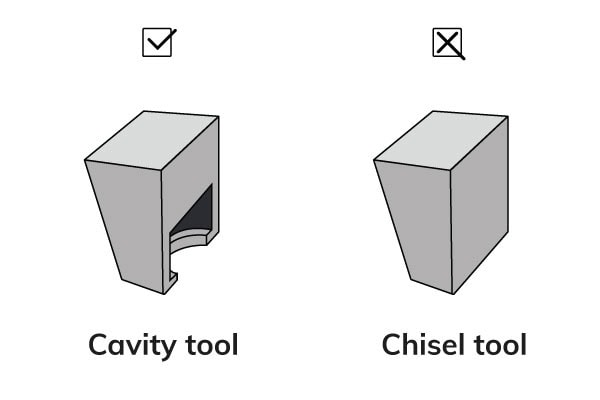
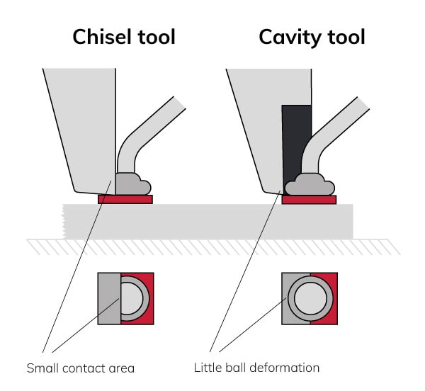
Cavity Shear tools have a semi-cylindrical recess (cavity) that distributes the shear load on a ball over a much larger surface area. This reduces ball deformation and increases the test result values. More bond failures provide more data on the bond’s strength than gold’s shear strength.
Instead of the failure mode of interest, try to get the highest bond strength possible by increasing the contact area of the tool to the ball using a cavity shear tool with a semi-cylindrical cavity.
The traditional chisel tool causes ball deformation due to a small contact area. A cavity shear tool causes less ball deformation and can result in more failure modes of interest.
The passivation layer in ultra-fine pitch applications often limits the shear height causing low test results as the tool simply cuts the top off the bond. Cavity shear minimizes this effect by distributing the test load over the ball. The advantages of cavity shear also apply to solder ball applications.
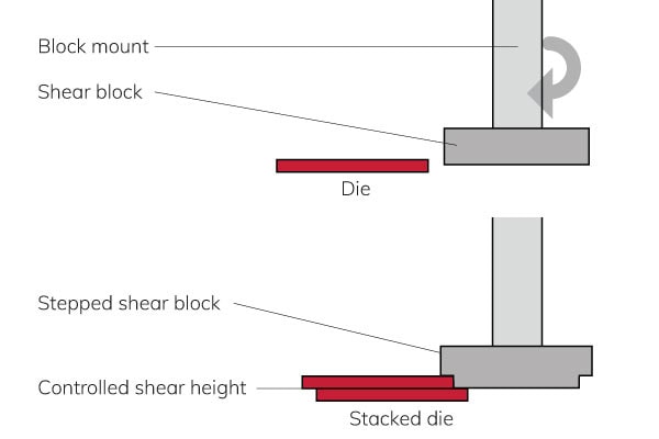
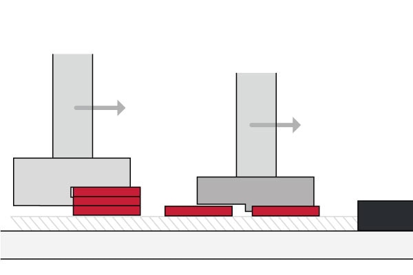
Overhanging die
Overhanging die shear tests are the perfect solution for testing stacked devices. But this requires precise tool landing and alignment. In addition, the overhanging die can cause inconsistent shear height because the tool landing force and shear down thrust will change the shear height.
There is no way to eliminate the deflection, but it is possible to minimize it. A programmable landing force of 2 grams reduces the deflection when landing, improving the step-back accuracy.
Passivation shear
If a bond shear height is too high, it will not give the failure mode of interest nor fail at the highest test force possible.
If the passivation layer is thick, it might result in shear height that is higher than optimal. This can result in no failure modes of interest and a low test force.
In a passivation shear test, the tool is sharp to attain the suitable shear height by cutting with a step down into the passivation.
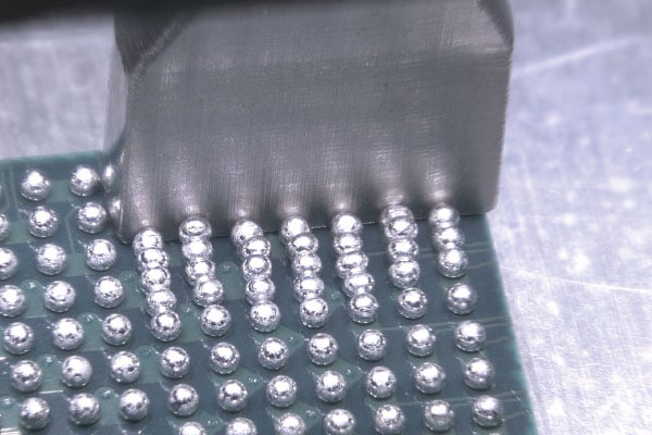
Zone shear
Zone shear or Total Ball Shear (TBS) tests all or many rows of balls in one operation, producing more bond or pad failures. The measurement metric is the number of bond failures related to bond strength. Unlike conventional shear, it can test the whole component in one pass.
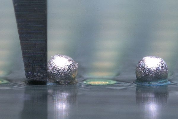
Failure mechanism
Below is an example of the failure mechanism. The rotation of the second ball is not free. This requires some sliding at the contacts because of ball deformation at the contact points.
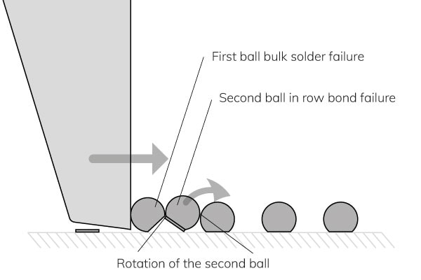
When the second ball in the row fails, its restricted movement produces a bulk solder failure, even though the first ball sheared it. The movement of the third ball in the row is less restricted because it is loaded by the second ball, which can easily move.
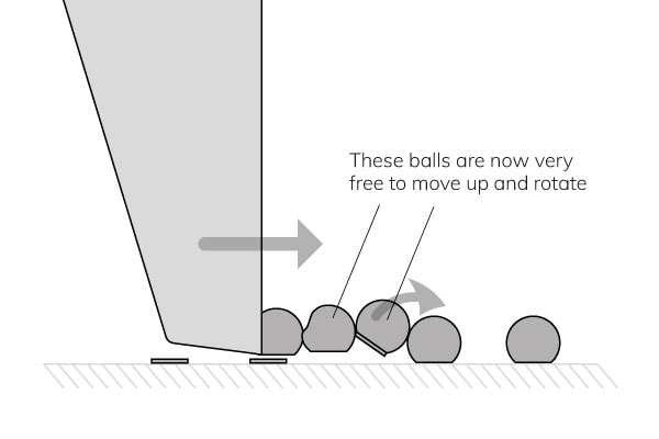
The sudden load release on the third row causes these balls to fly out. So, after the failure of row one, we are back to the loading condition.
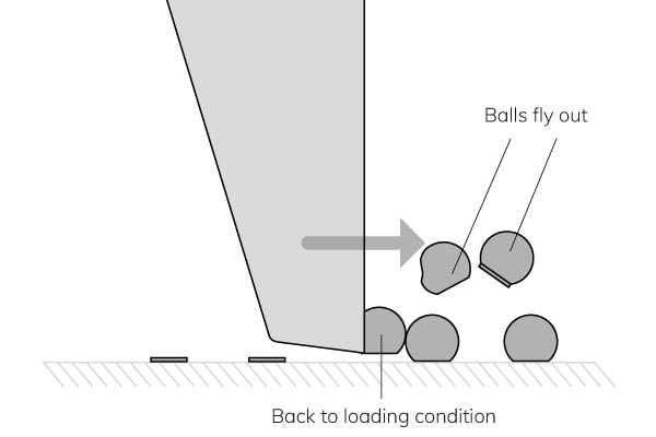
The first ball may also fly off after the third ball’s failure, but it does tend to stick to the tool. In this case, the cycle repeats at the fourth ball in the row.

Note that the typical importance of tool shear height is less critical for balls generally tested by the previous ball. Therefore, it is an estimation that a shear height between 1% to 15% of the ball height is acceptable.
Thin die/high force
Developments in die result in changes to component size and thickness. The latest chip packaging designs require stacked die or silicon bonded to silicon that results in changes to both the shape of the components and their bond strength.
3 aspects of designs make testing difficult:
- Reduced ratio of die thickness to die bond area
- Die and substrate warpage with thin die
- Silicon directly bonded to silicon or other similar materials (increases bond strength)
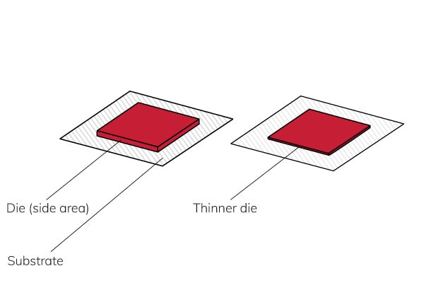
Reduce ratio of die thickness to die bond area
Reducing the ratio of the die thickness to the die bond area is relevant to shear testing. The practical issue is reducing the test load area to the bond area as the die becomes thinner. The shear tool applies the test load to the side area of the die.
When the die is thinner, there is less area to apply the test load. As the die thickness reduces, there comes the point when the test load stress between the tool and the die reaches its yield value before the bond reaches its yield stress. Then, the die fails before the bond fails without measuring the bond strength.
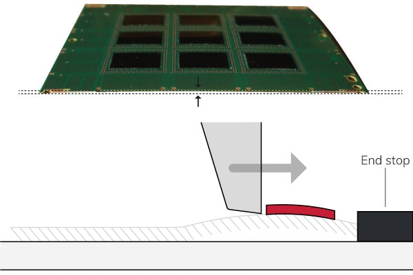
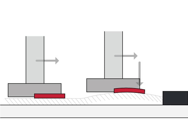
Die and substrate warpage with thin die
Warped die and substrates increase buckling loads on the die that can cause it to fracture before the bond fails.
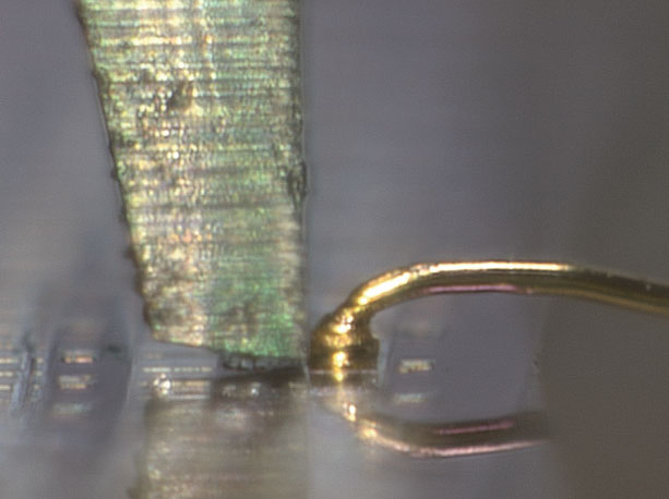
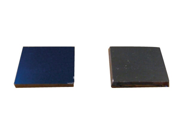
Silicon directly bonded to silicon or other similar materials (increases bond strength)
The picture below shows a silicon-to-silicon bond with similar yield stress to silicon. As the area of the bond is much larger than the area for the test load, the die will fail at the point of test load application before the bond. Therefore, it is often not possible to test samples like these.
Failure modes
A bond test should always strive to obtain the failure mode of interest, which will be a bond failure of some kind. To obtain a bond failure’s failure mode of interest, try to load the bond to the highest force possible.
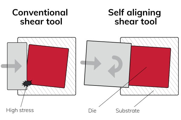
Self-aligning shear tool
With a self-aligning tool, it is possible to load the complete shear area evenly. The self-aligning shear tool freely rotates to match the die orientation. A conventional shear tool may cause higher stresses at the initial contact point, resulting in early die fracture.
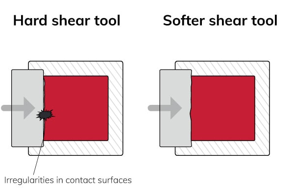
A hard shear tool causes stress concentration at the point of contact. A soft tool can load all sides evenly and deforms to die surface reducing stress concentrations. Soft tools typically last for about 10 tests, but this depends very much on the application. The parts are low-cost and easy to remove and fit.
It is important to engage with the full available height along the edge of the die. For bonds with a fillet the tool tip must be just above it. For flip chips, the tool must descend lower than the bottom of the die to be sure of full engagement but still be above the substrate.
Programmable landing force
In certain applications, there are advantages to referencing the test height of the test target itself rather than the substrate on which the target is placed. This is a “top landing” approach because the tool lands on top of the target rather than the substrate.
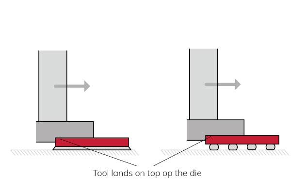
Top landing requires different forces for different applications, requiring a programmable landing force.
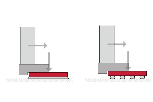
Landing on the top of the die with a slight landing force can also help minimize the effects of warpage by flattening the die between the tool and the work holder base.
It is also possible to use top landing to load a stacked die sample or to test dies close to each other.
Contact area
Use a 45° tool to increase the shear tool contact area further. The self-aligning shear tool freely rotates to match the die along two sides of the die. The work holder can have bearings normal to the shear direction to allow the die to center to the tool. A contact area over two sides of the die makes the area equivalent to a contact the same length as the diagonal.
If the die is square the area increases by a factor of 2 = 1.414 which means a 41% increase.

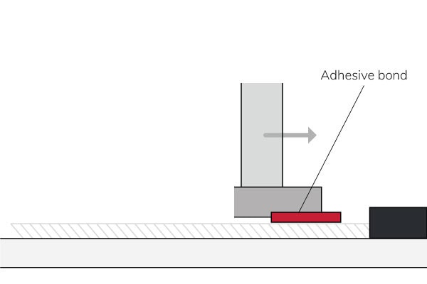
In specific unique applications, generating an adhesive bond and gluing a sacrificial block on top of the die may be necessary. This is most common when the bond strength is high and the die is thin.
Vector Shear
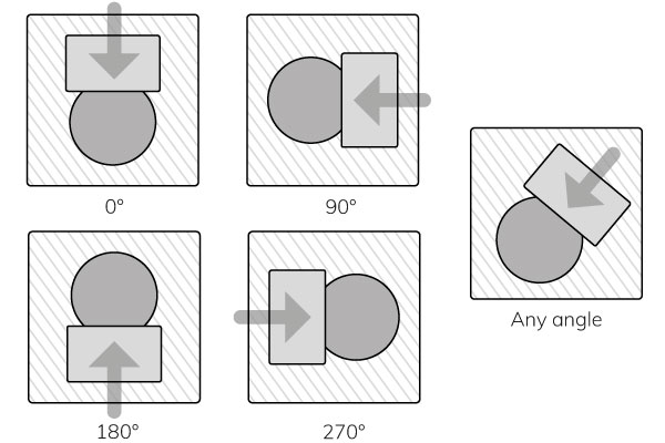
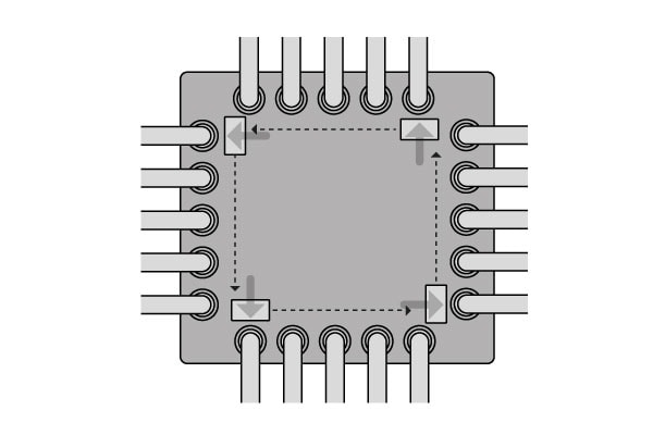
Vector shear allows programmable control of the shear direction in the XY plane. A vector shear rotates through 360° and shears in the chosen direction. The angle can be programmable, and any angle is achievable under joystick control. It is beneficial when testing all the first bonds on a chip.
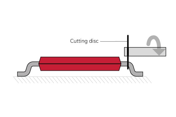
SMT gull wing leads
The best way to test the bond of an SMT gull wing lead is to cut the body from the leads and then test each lead.
Both cases will test the bond without affecting the body and the other leads. Testing without cutting the body off is possible. However, the body supports the leads.

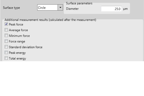
Test method
The test method allows programming the test variables. The basic test settings contain:
- Test distance
- Test speed
- Destructive or non-destructive test.
There are many more settings. Combining all settings in extraordinary ways is possible to solve all challenges smartly.
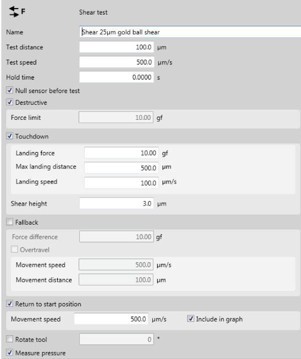
Test settings
Hold time
The hold time is most relevant for non-destructive tests. After setting the maximum force, the bond tester will hold this force for a certain time before moving back.
Force limit
The system will only increase the force until the specified limit and move back without destroying the sample.
Null sensor before test
Nulling the sensor before almost every test type is optional to prevent influences from residual forces on the tool or drift.
Fall back
When defining a fallback to determine the end of the test, the force difference is the most relevant value to set.
Rotate tool
Optional to set for vector shear.
Remember test settings
Sigma bond testers automatically store test method settings in one place to track method changes over time. Easily request previous test method settings behind a ‘show history’ checkbox.
Sigma bond tester
A Sigma bond tester is the most advanced bondtester for solder ball testing. It comes with game-changing automation capabilities and high specifications in:
- Sensor accuracy and resolution
- Large X stage
- Superior axis speed
- Cameras and illumination
- Future proof and modular design
Contact us and challenge us to customize a bond tester to solve your quality control processes.
