MIL-STD-883 method 2011.9 – Bond strength (destructive bond pull test)
Purpose
The purpose of this test is to measure bond strengths, evaluate bond strength distributions, or determine compliance with specified bond strength requirements of the applicable acquisition document. This test may be applied to the wire-to-die bond, wire-to-substrate bond, or the wire-to-package lead bond inside the package of wire-connected microelectronic devices bonded by soldering, thermocompression, ultrasonic, or related techniques. It may also be applied to bonds external to the device such as those from device terminals-to-substrate or wiring board or to internal bonds between die and substrate in non-wire-bonded device configurations such as beam lead or flip-chip devices.
Apparatus
The apparatus for this test shall consist of suitable equipment for applying the specified stress to the bond, lead wire, or terminal as required in the specified test condition. A calibrated measurement and indication of the applied stress in grams force (gf) shall be provided by equipment capable of measuring stresses up to twice the specified minimum limit value, with an accuracy of ±5 percent or ±0.3 gf, whichever is the greater tolerance.
Procedure
The test shall be conducted using the test condition specified in the applicable acquisition document consistent with the particular device construction. All bond pulls shall be counted and the specified sampling, acceptance, and added sample provisions shall be observed, as applicable. Unless otherwise specified, for conditions A, C, and D, the sample size number specified for the bond strength test shall determine the minimum sample size in terms of the minimum number of bond pulls to be accomplished rather than the number of complete devices in the sample, except that the required number of bond pulls shall be randomly selected from a minimum of 4 devices. Bond pulls in accordance with test conditions D, F, G, and H, while involving two or more bonds shall count as a single pull for bond strength and sample size number purposes. Unless otherwise specified, for conditions F, G, and H the sample size number specified shall determine the number of die to be tested (not bonds). For hybrid or multichip devices (all conditions), a minimum of 4 die or use all die if four are not available on a minimum of 2 completed devices shall be used. Where there is any adhesive, encapsulant or other material under, on or surrounding the die such as to increase the apparent bond strength, the bond strength test shall be performed prior to application. The stress required to achieve bond failure shall be observed and the physical location of the point of failure shall be recorded as being in one of the listed categories (see failure criteria).
When flip-chip or beam-lead chips are bonded to substrates other than those in completed devices, the following conditions shall apply:
Test conditions
Test condition A: Bond peel
This test is normally employed for bonds external to the device package. The lead or terminal and the device package shall be gripped or clamped in such a manner that a peeling stress is exerted with the specified angle between the lead or terminal and the board or substrate. Unless otherwise specified, an angle of 90 degrees shall be used. When a failure occurs, the force causing the failure and the failure category shall be recorded.
Test condition C: Wire pull (single bond)
This test is normally employed for internal bonds at the die or substrate and the lead frame of microelectronic devices. The wire connecting the die or substrate shall be cut so as to provide two ends accessible for pull test. In the case of short wire runs, it may be necessary to cut the wire close to one termination in order to allow pull test at the opposite termination. The wire shall be gripped in a suitable device and simple pulling action applied to the wire or to the device (with the wire clamped) in such a manner that the force is applied approximately normal to the surface of the die or substrate. When a failure occurs, the force causing the failure and the failure category shall be recorded.
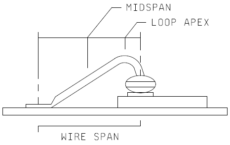
Test condition D: Wire pull (double bond)
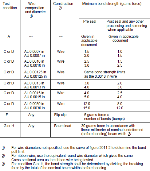
This procedure is identical to that of test condition C, except that the pull is applied by inserting a hook under the lead wire (attached to die, substrate or header or both ends) with the device clamped and hook contacting the wire between midspan and loop apex, without causing adverse wire deformation (for forward wedge and ball bonding, this would be between midspan and the die edge: for reverse bonding, this would be between midspan and the package edge) and the pulling force is applied in a perpendicular direction to the die or substrate surface. See Figure 2011-1. When a failure occurs, the force causing the failure and the failure category shall be recorded. The minimum bond strength shall be taken from table I. Figure 2011-2 may be used for wire diameters not specified in table I. For wire diameter or equivalent cross-section >0.005 inch, where a hook will not fit under the wire, a suitable clamp can be used in lieu of a hook.
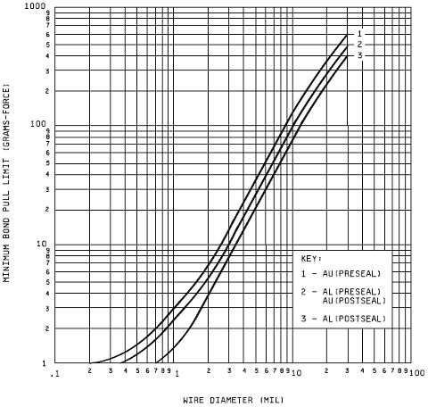
NOTE: The minimum bond strength should be taken from table I. Figure 2011-2 may be used for wire diameters not specified in table I.
Test condition F: Bond shear (flip chip)
This test is normally employed for internal bonds between a semiconductor die and a substrate to which it is attached in a face-bonded configuration. It may also be used to test the bonds between a substrate and an intermediate carrier or secondary substrate to which the die is mounted. A suitable tool or wedge shall be brought in contact with the die (or carrier) at a point just above the primary substrate and a force applied perpendicular to one edge of the die (or carrier) and parallel to the primary substrate, to cause bond failure by shear. When a failure occurs, the force at the time of failure, and the failure category shall be recorded.
Test condition G: Push-off test (beam lead)
This test is normally employed for process control and is used on a sample of semiconductor die bonded to a specially prepared substrate. Therefore, it cannot be used for random sampling of production or inspection lots. A metallized substrate containing a hole shall be employed. The hole appropriately centered, shall be sufficiently large to provide clearance for a push tool, but not large enough to interfere with the bonding areas. The push tool shall be sufficiently large to minimize device cracking during testing, but not large enough to contact the beam leads in the anchor bond area. Proceed with push-off tests as follows: The substrate shall be rigidly held and the push tool inserted through the hole. The contact of the push tool to the silicon device shall be made without appreciable impact (less than 0.01 inch/minute (0.254 mm/minute) and forced against the underside of the bonded device at a constant rate. When failure occurs, the force at the time of failure, and the failure category shall be recorded.
Test condition H: Pull-off test (beam lead)
This test is normally employed on a sample basis on beam lead devices which have been bonded down on a ceramic or other suitable substrate. The calibrated pull-off apparatus shall include a pull-off rod (for instance, a current loop of nichrome or Kovar wire) to make connection with a hard setting adhesive material (for instance, heat sensitive polyvinyl acetate resin glue) on the back (top side) of the beam lead die. The substrate shall be rigidly installed in the pull-off fixture and the pull-off rod shall make firm mechanical connection to the adhesive material. The device shall be pulled within 5 degrees of the normal to at least the calculated force (see procedure), or until the die is at 2.54 mm (0.10 inch) above the substrate. When a failure occurs, the force at the time of failure, the calculated force limit, and the failure category shall be recorded.
Wire Ball Bond Shear
Procedure in accordance with JEDEC JESD22-B116 Wire Bond Shear Test Method.
Failure criteria
Any bond pull which results in separation under an applied stress less than that indicated in table I as the required minimum bond strength for the indicated test condition, composition, and construction shall constitute a failure.
Failure category
Failure categories are as follows: When specified, the stress required to achieve separation and the category of separation or failure shall be recorded.
For internal wire bonds:
- Wire break at neckdown point (reduction of cross section due to bonding process).
- Wire break at point other than neckdown.
- Failure in bond (interface between wire and metallization) at die.
- Failure in bond (interface between wire and metallization) at substrate, package post, or other than die.
- Lifted metallization from die.
- Lifted metallization from substrate or package post.
- Fracture of die.
- Fracture of substrate.
For external bonds connecting device to wiring board or substrate:
- Lead or terminal break at deformation point (weld affected region).
- Lead or terminal break at point not affected by bonding process.
- Failure in bond interface (in solder or at point of weld interface between lead or terminal and the board or substrate conductor to which the bond was made).
- Conductor lifted from board or substrate.
- Fracture within board or substrate.
For flip-chip configurations:
- Failure in the bond material or pedestal, if applicable.
- Fracture of die (or carrier) or substrate (removal of portion of die or substrate immediately under the bond).
- Lifted metallization (separation of metallization or bonding pedestal from die (or carrier) or substrate.
For beam lead devices:
- Silicon broken.
- Beam lifting on silicon.
- Beam broken at bond.
- Beam broken at edge of silicon.
- Beam broken between bond and edge of silicon.
- Bond lifted.
- Lifted metallization (separation of metallization) from die, separation of bonding pad.
- Lifted metallization.
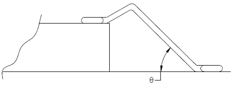
Note: RF/microwave hybrids that require extremely flat loops which may cause erroneous wire pull data may use the following formula to determine the proper wire pull value.
V1 = V2 sin Θ
Where:
V1 = New Value to pull test.
V2 = Table I value for size wire tested
Θ = Greatest calculated wire loop angle (Figure 2011-3).
Also, RF/microwave hybrids that contain wires that cannot be accessed with a pull hook must be duplicated on a test coupon in such a way to allow hook access for purposes of pull testing. These wires are to be bonded at the same time the production hybrids are bonded using the same setup, operator, and schedule. The test coupon wires are to be pull tested in lieu of the tuning or inaccessible wires on the production hybrid. Failures on the test coupon shall be considered as failures to production units and appropriate action is to be taken in accordance with the applicable specification (Figure 2011-4).
Summary
The following details shall be specified in the applicable acquisition document:
