Why test bonds?
Electrical and thermal bonds are such an integral part of electronic and semiconductor construction that they may often be taken for granted. Modern electronic assembly methods employ a myriad of bonding processes, each one a vital step in the manufacture of the final product. A typical consumer product such as a laptop computer may contain hundreds of thousands of bonds yet if one fails it will probably result in a system breakdown.
Introduction
Bond strength measurement is far from the highest profile portion of the electronic and semiconductor industries but it has matured with it, in some cases unnoticed. This doesn’t alter the fact that a precise knowledge of bond strength quality measurement during product design and subsequent manufacture is directly related to product success, customer satisfaction and profitability.

To serve this need a modern bond test system must be capable of accurately testing bond wires, solder bumps, dies, leads, chips, lids as well as other applications with strengths varying from a few grams of force to as much as hundreds of kilograms of force. Investigating the roots of bond testing, outlining what is required to perform a good bond test and what a modern bond tester should be capable of performing is essential in defining an accurate bond testing protocol.
Getting back to basics, why measure bond strength in the first place? Bonds fail either in production or end use and these failures can be caused by their geometry, material or processing factors. These factors greatly affect and ultimately define the quality and integrity of the bond. Measuring bond strength is then a useful tool during the design process and for quality control to minimize product variability, ensure manufacturing yield and increase end product reliability.
Bond testing has been around for so long you might not have thought what it is really for and how it should be done? The basic types of bond testing include pull and shear which are applied to either the destruction of the bond or to some force below this value in the form of a non destructive test. A push test is sometimes used but this is closely related to the pull test.
Non destructive tests are normally used when extreme reliability is required such as in military or aerospace applications. In these cases, every bond is tested to ensure the utmost quality level making this routine relatively time consuming and costly. More commonly bonds are tested to destruction on a batch sampling basis with the peak force and failure mode being recorded for statistical analysis. This is indeed a good starting point but requires examination in more detail. The best place to start is with the failure mode. This is based on the assumption that there is a particular failure mode, or range of modes, that may occur within a product. It is therefore reasonable to assume that the bond test should replicate the mode, or modes of interest. However, exact replication is not always possible. The test load must be applied to some part of the sample and transferred through the sample to the bond. If this part of the sample is the only option and is weaker than the bond itself, the sample will fail before the bond.
Shear Testing
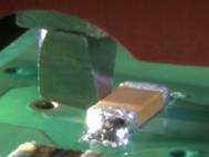
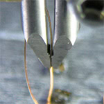
A good example of this is shear testing of a gold ball bond and wire bonds within a semiconductor device (Figure 1). A good gold ball bond will be stronger than the ball so the failure mode of a strong bond will be gold ball shear. It is not uncommon for production engineers to use this failure mode alone as an indication of bond strength but it does represent a limit to the capability of the test. A better test would produce a bond failure and record a higher force that corresponds with the bond strength. One of the prime objectives of a bond test designer is to try to produce the failure mode of interest.

As mentioned peak force is by far the most common metric for measuring bond strength. This is very often all that is needed but a force-displacement graph conveys a lot more information. Traditionally force time was recorded because this is relatively easy to obtain but it is far less interesting. If the test is done at constant speed the difference between a force-time and force-displacement graph is only one of scale on the X-axis typically denoting time or displacement.
However, when testing with small bond deflections, high forces or at moderate test speeds maintaining a constant test velocity can be extremely difficult. In these cases a velocity-time graph may lead to a misinterpretation of the test results. Using displacement one can visualize the force increasing and falling as the bond yields relate directly to the geometry of the sample. In addition the area of the force-displacement graph equals the energy absorbed by the bond which in itself is an alternative bond strength metric that is particularly valuable when testing resistance to mechanical shock.
As previously mentioned, obtaining an accurate force-displacement graph can be challenging. In rigid bonds such as a die attach the deformation of the bond to failure is extremely small and typically less that the deformation that occurs in a well designed test machine performing the test. The best way to overcome this is to use an external displacement sensor that directly measures the deflection of the tool applying the load to a datum point on the sample synchronously with the force measurement. Such a system typically requires nanometer resolution. The good news is that peak force is often all that is needed for this type of test and this is not affected by the types of errors that are typically seen in a displacement measurement.
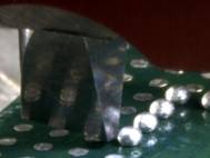
Another use of the force-displacement graph is in bond strength modeling. This is of growing interest driven by the possibility that the strength and reliability of a bond may be virtually guaranteed during the design process. Given the massive range of geometries, materials and processes used this is no small undertaking. However, particular designs can be modeled and the model qualified by a bond test. The assumption being that if the model successfully predicts the failure mode and force-displacement of a given bond test, there is a very good chance it will also make an accurate prediction modeling of a reallife loading condition. We should be aware that no bond test exactly replicates the real thing. For example when a chip capacitor bond breaks it is not because a shear tool has subjected it to a load (Figure 2).
Like any experiment the act of the measurement process can potentially change the measurement. Bond testing is typically a strength analog or comparator but none the less is an essential control tool in assuring product quality in electronic assemblies.
Solder Bump Testing
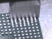
For many years solder bumps have been sheared at speeds of less than 1mm/second. It has been found that testing at these speeds almost always produces failures in the bulk solder but manufacturing and end use failures occur in the bond interface. Recent developments have shown that testing at speeds in the range of hundreds or thousands of millimeters per second more often produce the ‘failure mode of interest’ at the bond interface which is therefore much more meaningful (Figure 3).
Holding the sample is of equal importance. In many bond test applications sub-micron precision is required while in other cases forces of up to hundreds of kilograms of force are often a requirement. High force applications of up to 500 kilograms (kgf) means that great attention be applied to this detail together with the contribution of a skilled or knowledgeable technician as one of the keys to ensure quality results. Standard fixtures are often used but this sometimes requires modification or custom tooling has to be designed to hold the sample. Clamping is normally required to fully support the sample when it is subjected to the test load but in such a fashion that the bond is not stressed and negligible sample deflection occurs.
Die Pull Applications
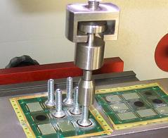
Die pull also referred to as stud pull, has been used for many years as an alternative loading condition to the more frequently used shear test. It is generally a more difficult test since a stud has to be glued to the die which can then be pulled to test the bond (Figure 4). The strength of the adhesive bond between the die and the stud will limit the maximum load that can be applied to the bond. Adhesive strengths of around 20 to 30 megapascal (MPa) are possible and current research is trying to increase this limit to 45 MPa. The increase in stacked die and wafer-to-wafer applications using multiple layers of silicon is driving a corresponding increase in this type of test. It also has relevance when a layer or die is very thin and the stress concentration on the side of the sample exceeds its yield stress in a shear test. In these cases the stud pull test distributes the load over the larger top surface.
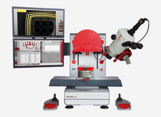
Ease of use is another fundamental requirement of any bond testing system. Any complex measurement system potentially runs the risk of producing errors due to operator misunderstandings and or fatigue. Ease of use also directly affects throughput and cost of ownership. The most common interface with the operator or engineer is that the software must be straightforward, intuitive and yet comprehensive and flexible for the very wide range of bond testing applications it must serve. Hardware is also important, starting with the loading of a sample through to continuous and easy testing. Controls and optics, usually a stereo zoom microscope, must be conveniently and ergonomically placed.
A final ingredient in a bond tester is flexibility. There are many differing demands made upon a modern bond testing system. To serve this range of applications the machine must be flexible for the wide variety of tests and samples. Some requirements are narrow and so the system must be configurable to a cost effective solution. Other requirements can be varied and so the same configurability can be used to enable on-site changeover for a wide variety of applications. To achieve this, a range of various frame sizes are needed that have an open layout with accurate and long travel axes coupled to an easy way of changing between test sensors. In effect, a multifunctional bond tester equipped with automatic selection of pull, shear and impact tools and interchangeable revolving measurement unit and impact measurement unit sensors has a high degree of versatility and is capable of bond testing a wide variety of semiconductor and printed circuit board assembly applications.
Conclusion
The subject of bond testing is far ranging and varied but the value that it contributes to ensuring product quality cannot be overlooked. Precise force displacement measurement using a modern bond tester allows bond strength modeling that can successfully predict the various failure modes and can be used as an accurate prediction model of real life loading conditions.
This article originally appeared in the June 2010 issue of Global SMT & Packaging magazine